Brake beam structure

a technology of brake beams and beams, which is applied in the direction of brake systems, railway components, transportation and packaging, etc., can solve the problems of rigidity of the same, high stress on certain parts and elements of the brake beam, and the same vulnerability to breakag

Inactive Publication Date: 2001-05-22
STUCKI DE MEXICO S DE R L DE C V
View PDF7 Cites 25 Cited by
  • Summary
  • Abstract
  • Description
  • Claims
  • Application Information

AI Technical Summary

Benefits of technology

It is another main objective of the present invention to provide a brake beam structure which has the flexibility of an assembled brake beam and in which an adequate distribution of high torsional and harmful forces along the whole brake beam is achieved.
It is still a main objective of the present invention to provide a brake beam structure which has a longer and more reliable lifetime.

Problems solved by technology

The simplest way to produce a brake beam is welding all the elements, without including any kind of fasteners, but the disadvantage of this kind of brake beam is the rigidity of the same, making the same very vulnerable to breakages.
These dangerous and harmful forces are translated to the compression and tension members and to the fulcrum, through the whole beam, causing a great stress in certain parts and elements of the brake beam when brakes are applied.
These harmful forces are specially high in the extremes of the brake beam where it is coupled to the bogie and where several components of the same are joined, such as the brake head, the tension member and compression member, making the extremes, critical points here a lot of harmful forces converge.
Due to the rigidity of the all welded brake beam, these harmful forces and high torsional moments cause breakages and a high wear, in the above referred points, and Often the components break during use.
Although Spaeth assembled structure is more flexible than the all welded brake beam, it has the same problem that is present in the all welded brake beam, which is an excess of harmful forces in the extremes of the brake beam, where the brake head and the tension and compression members converge in a similar way as in the all welded strut, which reduces the durability of the whole brake beam, and in some times the breaking of the same.
U.S. Pat. Nos. 2,722,291, 2,753,960 and 4,830,148, discloses the same type of assembling structure in which compression and tension members converge near each end of the beam and mount brake heads at the ends of the beam, which leads to the same disadvantages of the all welded brake beam and Spaeth brake beam.
The two fasteners disclosed in the Sandmann patent, add some strength to the critical points of the brake beam assembly, but during normal use, these fasteners are subject to an excess of harmful forces, because said fasteners are the only means that maintains the brake head and the tension and compression members joined together and therefore, said fasteners are under a constant and excessive stress receiving all the torsional forces of the brake heads and tension and compression members.
Said harmful forces produce, in addition of the above described problems present in this kind off assembling structure, a premature wear of the fasteners, and in a short period of time said fasteners may break, disassembling the brake head form the brake beam.

Method used


Image

  • Brake beam structure
  • Brake beam structure
  • Brake beam structure

Examples


Embodiment Construction

.

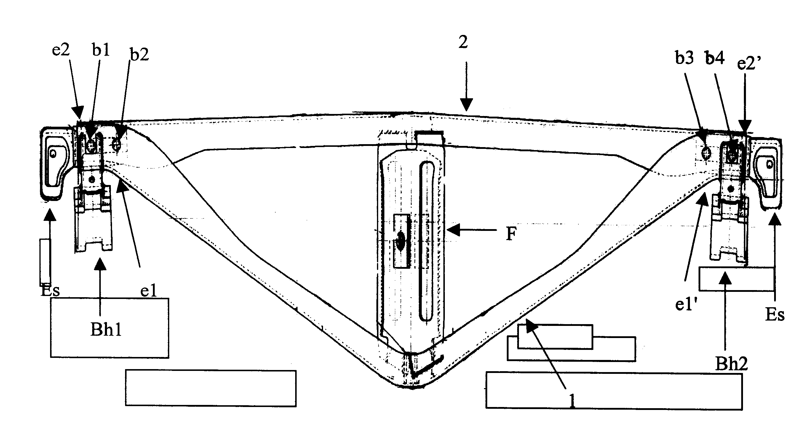
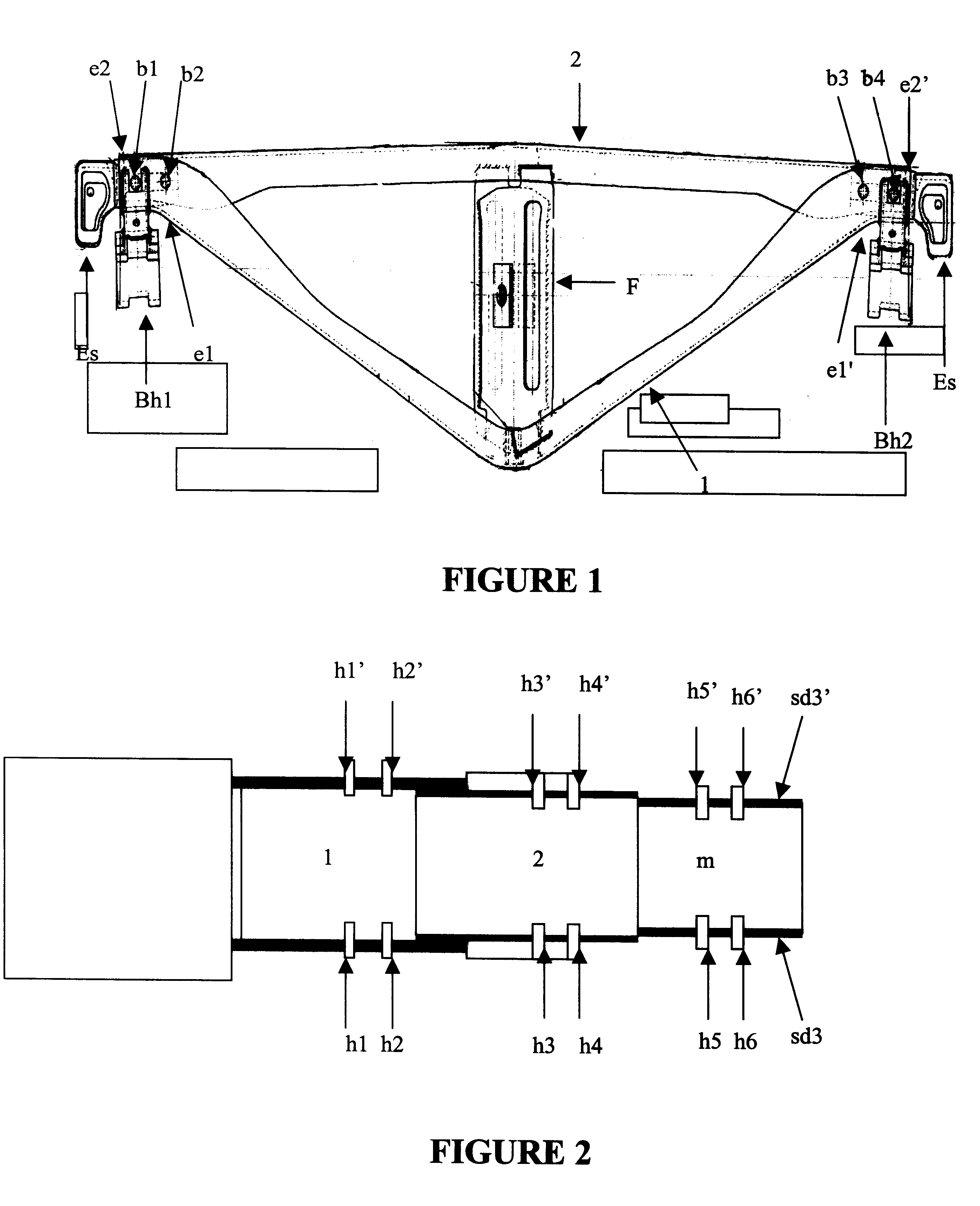
The brake beam of the present invention, will now be initially described in accordance with a preferred embodiment thereof, and making reference to FIGS. 1 to 5, comprises:

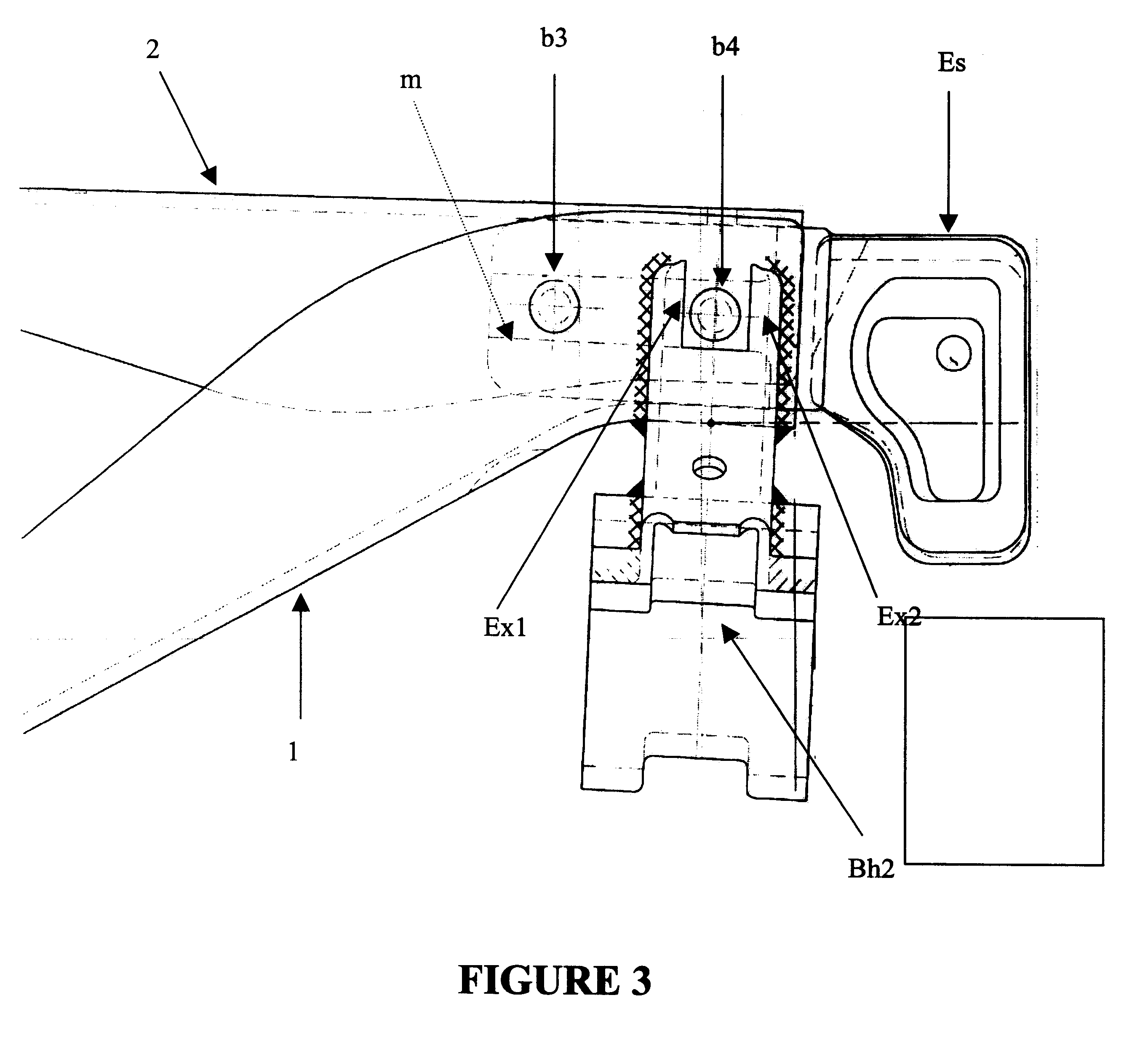
a "V" shaped tension member 1 having a first end e1 and a second end e1' having a channel shaped cross section including a lower wall lw1 which turns parallel to an horizontal axis at the ends of the tension member 1, and two upwardly projecting side walls sd1, sd1', each depending from an edge of the lower wall lw1' and each end having two pairs of opposite holes h1, h1', h2, h2' each longitudinally placed at each side wall sd1, sd1' at each end e1, e1' of the "v" shaped tension member. Said projecting side walls sd1, sd1', having a progressive widening at the ends e1, e1' of the tension member.

a compression member 2, having a first end e2 and a second end e2', each of which is placed inside the housing of the tension member channel shaped cross section at the ends e1, e1' of the tension member, said compression...


PUM


Abstract

A brake beam structure comprising compression and tension members having an "u" shaped cross section including two side walls and forming a housing, two end extensions having a quadrangular cross section including two side walls, a fulcrum coupled to the compression and tension members and two brake heads, in which: the ends of the compression member are placed inside the housing of the unshaped cross section of the tension member and each of the end extensions are placed inside the housing of the channel shaped cross section of the compression member, the brake beam having two fasteners passing through holes placed at the ends of the tension and compression members at each of "u" shaped cross section side walls and through holes placed at the side walls of the end extensions in order to fasten the tension member, compression member and end extensions, and in which the brake heads are welded to the ends of the tension member.

Description

BACKGROUND OF THE INVENTION.A. Field of the InventionThis invention relates to brake beams, and more particularly to a brake beam structure for railway cars in which the tension member, compression member and end extensions are joined by bolts and the brake head is welded to the tension member.B. Description of the Related ArtThere are well known brake heads assemblies for railway cars by which a brake shoe is pressed against a wheel in order to decrease or stop the rotational speed of the wheel and railway car.Generally, the brake head assembly is held by a structure called "brake beam" mounted transversely in the bogie of a railway car and is linked to a lever, which applies a force in order to press the brake shoe against a wheel.The brake beam generally comprises a compression member, a generally "V" shaped tension member having its ends coupled to the ends of the compression member, a brake shoe linked to the each end of the compression member, an end extension by which the bra...

Claims


Application Information

Patent Timeline
Patent Type & Authority Patents(United States)
IPC IPC(8): B60T1/04B60T1/00B60T11/06B61H13/36B60T11/00B61H13/00
CPCB60T1/04B60T11/06B61H13/36
Inventor MONTES-RAMOS, MIGUEL-ANGEL
Owner STUCKI DE MEXICO S DE R L DE C V
Why Eureka
Try Eureka