
Hydraulic running tool

a running tool and hydraulic technology, applied in the direction of drilling casings, drilling pipes, borehole/well accessories, etc., can solve the problems that the running tool cannot be released from the liner hanger in a weight down, and the design is therefore limiting in its operation

Inactive Publication Date: 2001-06-05
WEATHERFORD TECH HLDG LLC
View PDF13 Cites 97 Cited by
  • Summary
  • Abstract
  • Description
  • Claims
  • Application Information

AI Technical Summary

Problems solved by technology

However, this design requires holding or maintaining left hand torque on the pipe string while running into the well bore.
One problem with this design is that the running tool can only be released from the liner hanger in a weight down position.
This design is therefore limiting in its operation.

Method used


Image

  • Hydraulic running tool
  • Hydraulic running tool
  • Hydraulic running tool

Examples


Embodiment Construction

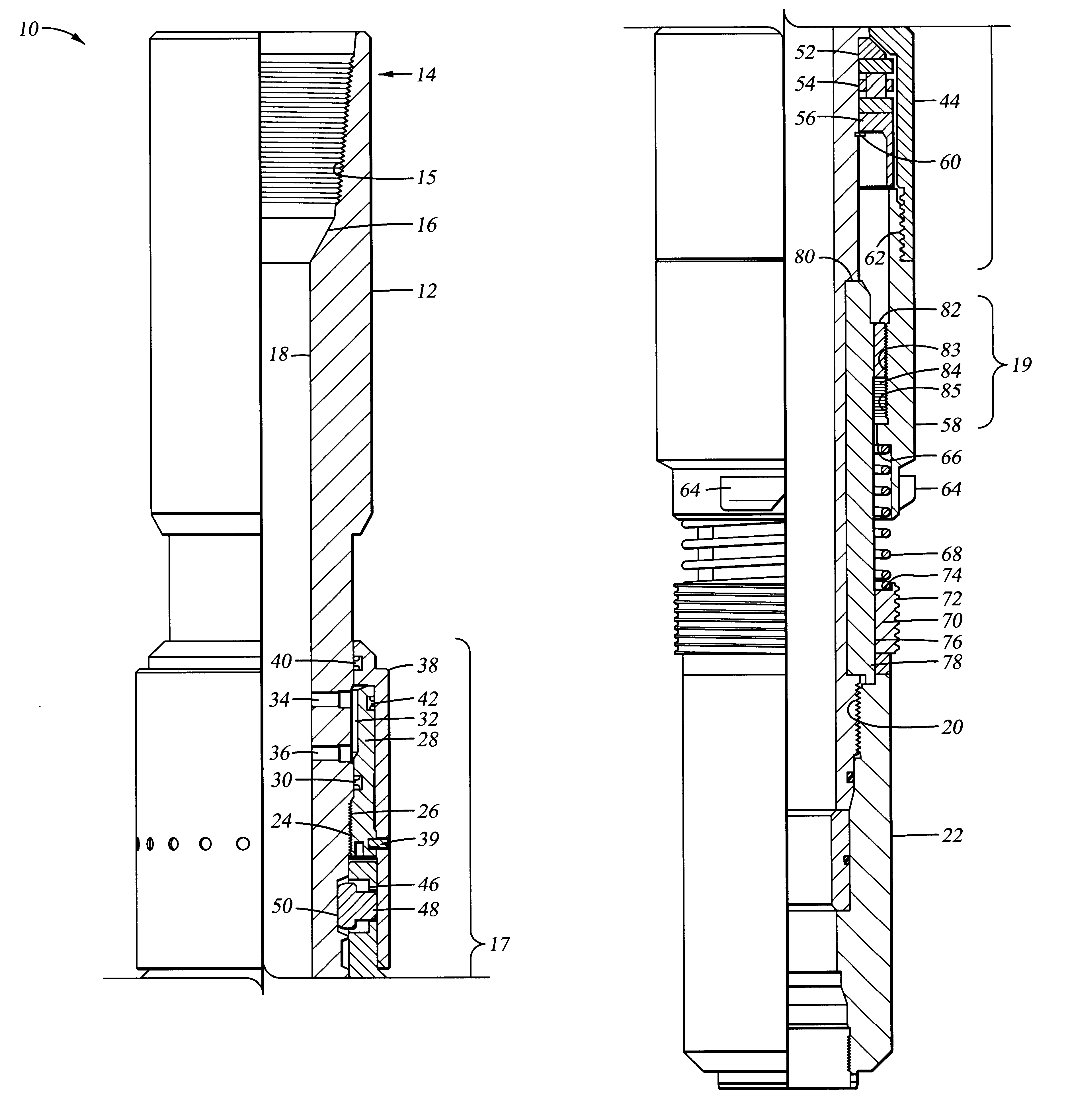
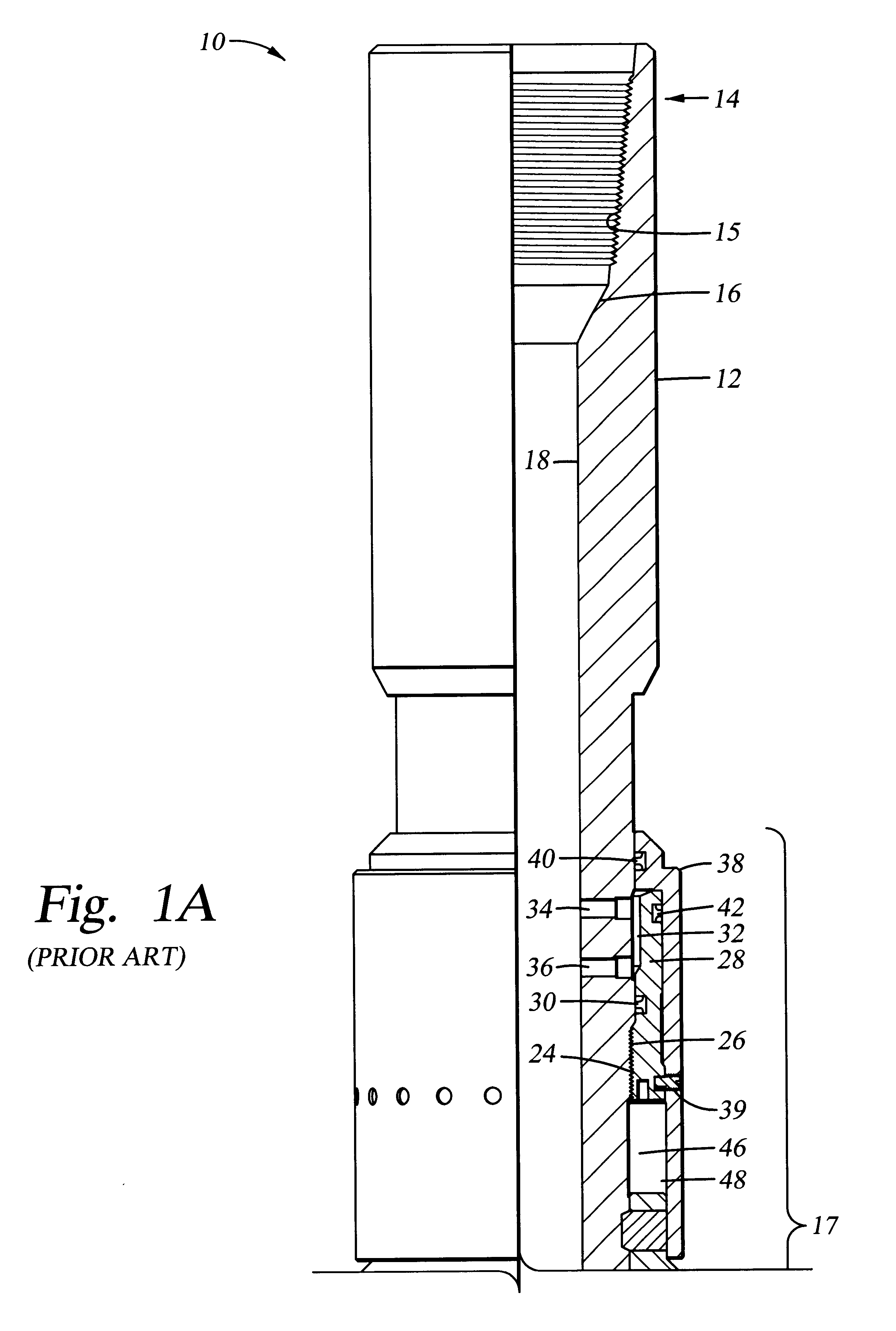
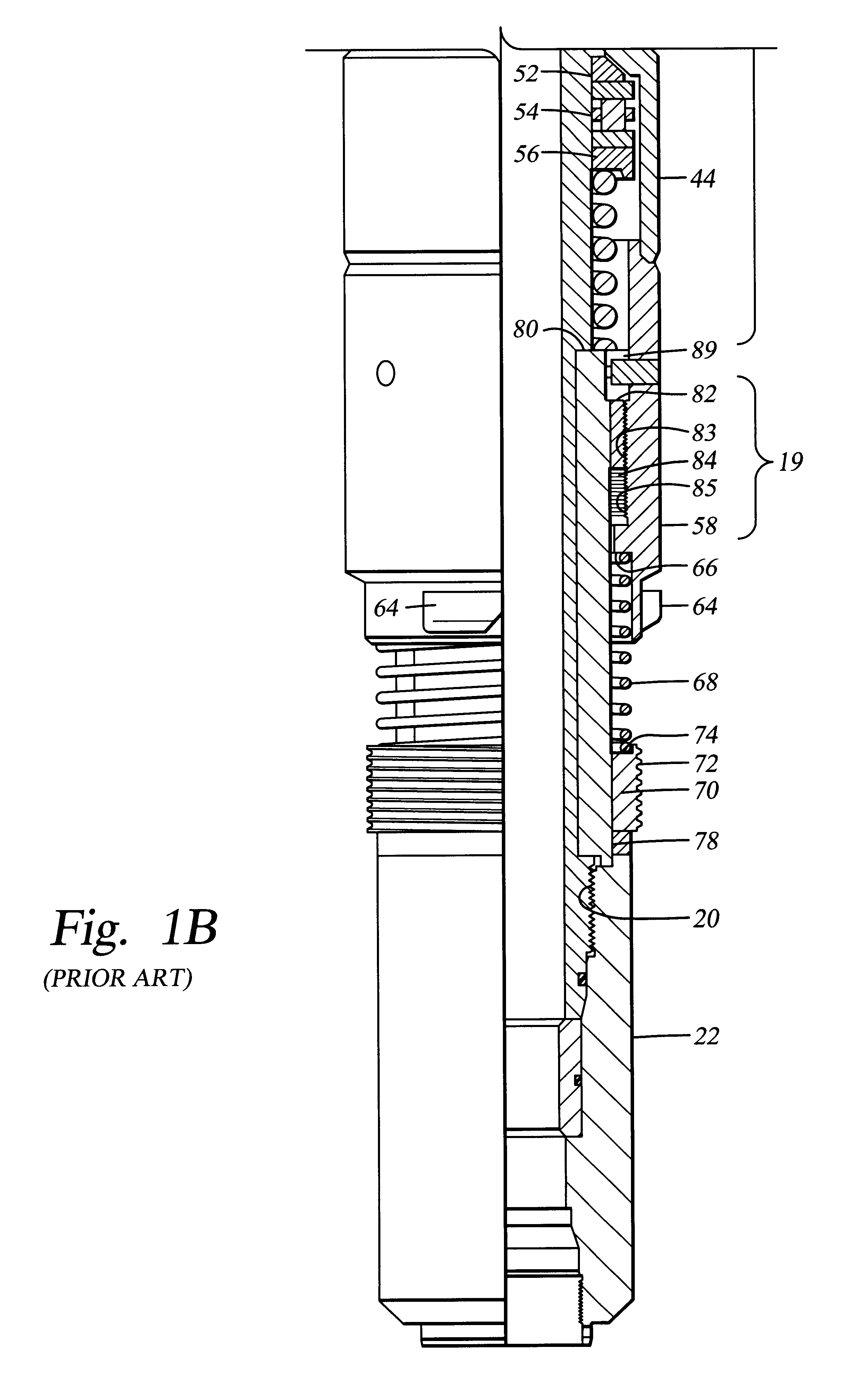
FIGS. 3a and 3b are side views in partial section of a running tool 10 according to one aspect of the invention in a running-in position adapted to be made up on a pipe string for releasably engaging a setting sleeve or liner hanger in a well bore. The invention generally includes a body 12 having a threaded connector 70, such as a float nut, disposed on its lower end and having an upper internally threaded portion 15 connectable to a pipe string (not shown). A latch assembly 17 is disposed on the body 12 to selectively transmit torque from the body 12 to at least a portion of the latch assembly 17. A lock assembly 19 is disposed at least partially between the latch assembly 17 and the body 12 to selectively transmit torque to a portion of the latch assembly when the lock assembly engages a portion of the latch assembly connected to a setting sleeve (not shown). The running tool 10 will now be described in more detail with reference to a preferred embodiment shown in FIGS. 3a, 3b, 4...


PUM


Abstract

The present invention generally provides a running tool which can be released using hydraulic pressure and can provide continued rotation to a liner hanger or other tool disposed below and rotationally connected to the running tool. In one aspect, a hydraulic assembly is provided to release a thrusting cap from rotation so that a threaded connection between the running tool and the liner hanger can be released. On release of the liner hanger, a lock nut travels down a threaded surface of the thrusting cap and engages the thrusting cap to continue rotation through the thrusting cap. Additionally, the running tool may include a mechanical release operable without the assistance of hydraulic pressure.

Description

1. Field of the InventionThe present invention relates generally to oil well running tools. More specifically, the invention relates to a running tool adapted to engage a setting sleeve on a drill pipe or tubing string in a well bore, and specifically to a running tool which allows right hand rotation to be used during well bore operations and to release the setting tool from the setting sleeve.2. Background of the InventionRunning tools are used for various purposes during well drilling and completion operations. For example, a running tool is typically used to set a liner hanger in a well bore. The running tool is made up in the drill pipe or tubing string between the liner hanger and the drill pipe or tubing string running to the surface. The running tool serves as a link to transmit torque to the liner hanger to place and secure the liner in the well bore. The running tool is then typically manipulated from the surface to effect release of the running tool from the liner hanger....

Claims


Application Information

Patent Timeline
IPC IPC(8): E21B43/10E21B43/02E21B17/06E21B23/04
CPCE21B17/06E21B23/04E21B43/10E21B23/0418
Inventor ERIKSEN, ERIK PETER
Owner WEATHERFORD TECH HLDG LLC
Features
  • Generate Ideas
  • Intellectual Property
  • Life Sciences
  • Materials
  • Tech Scout
  • Unparalleled Data Quality
  • Higher Quality Content
  • 60% Fewer Hallucinations
Learn More