Throwing and hitting sports toy

a sports toy and kicking technology, applied in the field of throwing sports toys, can solve the problems of difficult to confine baseball-type games to restricted areas such as indoor gyms or residential yards, and the additional distance of rolling,

Inactive Publication Date: 2001-06-12
DEPCIK DAVID F
View PDF12 Cites 9 Cited by
  • Summary
  • Abstract
  • Description
  • Claims
  • Application Information

AI Technical Summary

Benefits of technology

FIG. 3 is a partial cut-away view of another embodiment of the present invention;

Problems solved by technology

Additionally, when a ball is hit and lands it often rolls an additional distance.
The result is that it is often difficult to confine such baseball-type games to restricted areas such as an indoor gym or residential yard.
Furthermore, it is difficult to practice batting absent vast areas of open space or netting to catch and retrieve balls.

Method used


Image

  • Throwing and hitting sports toy
  • Throwing and hitting sports toy
  • Throwing and hitting sports toy

Examples


Embodiment Construction

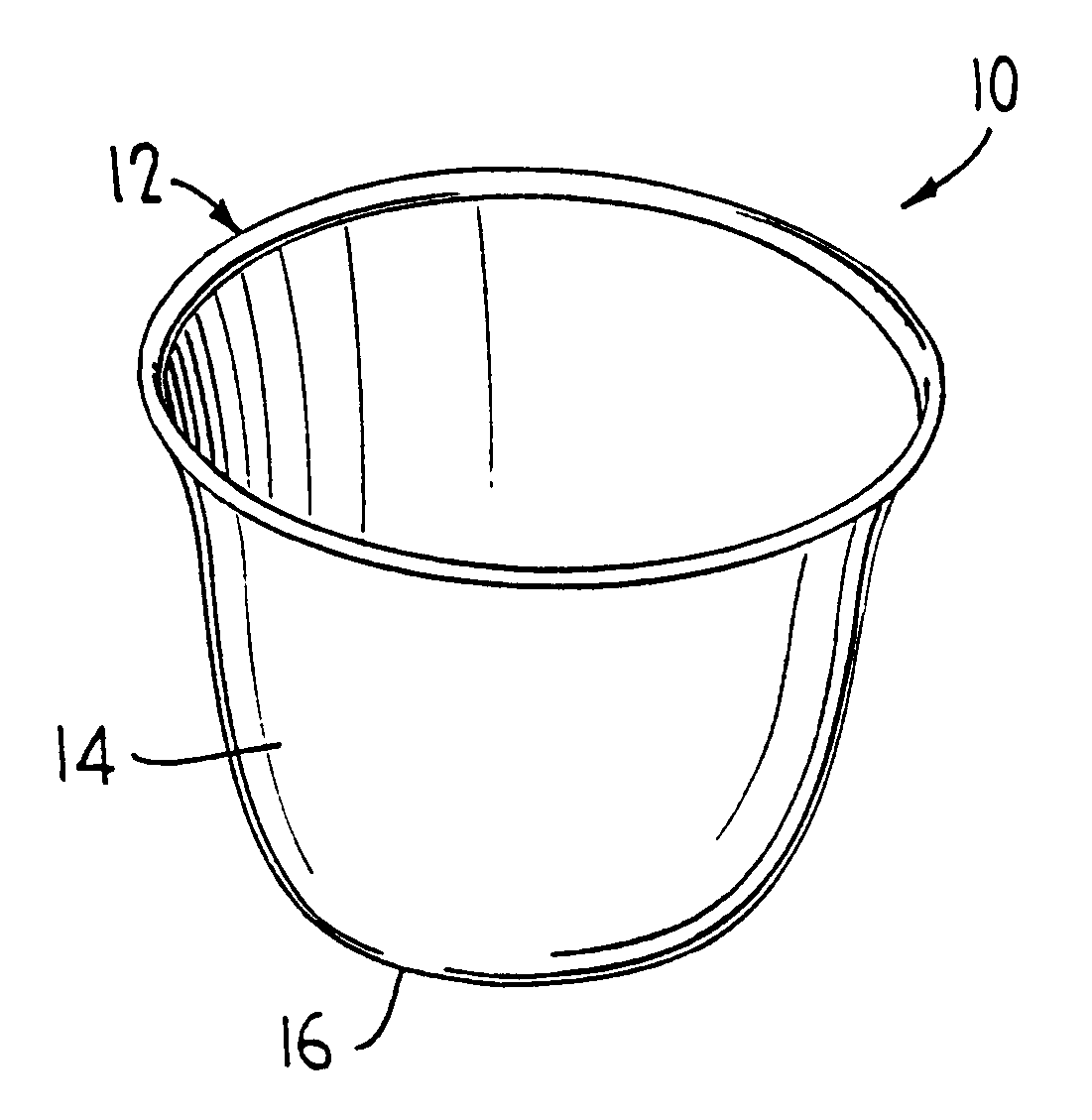
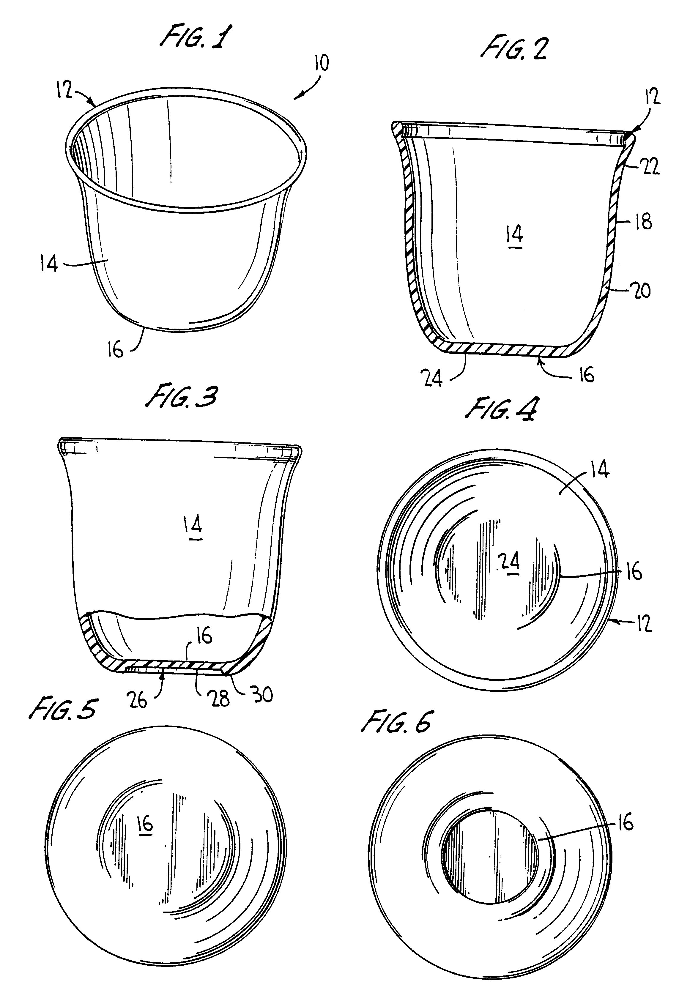
Referring to the drawings, wherein similar reference characters designate corresponding parts throughout the several views, the throwing and hitting sports toy of the present invention is generally illustrated at 10 in FIG. 1. The throwing and hitting toy is substantially cup-shaped and includes generally a flared open end portion 12, a body portion 14, and a closed end portion 16.

Turning to FIG. 2, the body portion 14, generally cylindrically shaped and analogous to the sidewalls of a cup, has a top end 18 and a bottom end 20. The top end 18 merges into a flared rim portion 22. FIG. 4 shows a top view of the invention looking into the flared open end 12. The bottom end 20 terminates generally at the closed end portion 16. The flared rim is of a greater circumference than the body portion 14 and is one aspect which can affect the flight pattern of the invention. The closed end portion 16, in the embodiment depicted in FIG. 2, has a substantially planar bottom portion 24 that is of s...


PUM


Abstract

A substantially cup-shaped throwing and hitting sports toy is provided having a flared open end portion, a body portion, and a closed end portion. The structure of the toy provides for various flight patterns while being suitable for use in limited areas of space.

Description

The invention is directed to throwing and hitting sports toys, particularly suitable for use in throw and hitting baseball-type games.Sporting activities involving throwing, catching, and / or hitting a thrown or flying object have become a popular pastime. Many types of balls and objects are known for use in sporting activities involving bats, such as baseballs, softballs, and "balloon" balls. Yet other balls and objects exist for striking with a flat surfaced article like a racket or paddle, such as tennis balls and badminton shuttlecocks. Further, many variations exist in the compositions and coverings of such balls or objects that may affect the aerodynamics, safety of use, durability, hardness, resiliency, elasticity, etc. of the balls or objects.Balls used in baseball-type games often travel great distances in the air after being hit by a bat. Additionally, when a ball is hit and lands it often rolls an additional distance. The result is that it is often difficult to confine suc...

Claims


Application Information

Patent Timeline
Patent Type & Authority Patents(United States)
IPC IPC(8): A63B65/00A63B59/00
CPCA63B65/00A63B59/00A63B2208/12
Inventor DEPCIK, DAVID F.
Owner DEPCIK DAVID F
Why Eureka
Try Eureka