Packer system

a packer system and wellbore technology, applied in the direction of borehole/well accessories, drilling casings, drilling pipes, etc., can solve the problems of ineffective ball actuated disconnect, inability to rotate coil tubing, and inability to use down-hole tools that require rotation

Inactive Publication Date: 2001-07-10
WEATHERFORD TECH HLDG LLC
View PDF67 Cites 85 Cited by
  • Summary
  • Abstract
  • Description
  • Claims
  • Application Information

AI Technical Summary

Problems solved by technology

Coil tubing cannot be rotated.
Certain prior art down-hole tools that require rotation cannot be used with coil tubing.
In certain prior art wellbore operations in which fluid with solids is being pumped into the wellbore (e.g. sand, proppant, or other solids), a ball actuated disconnect may be ineffective.

Method used


Image

  • Packer system
  • Packer system
  • Packer system

Examples


Embodiment Construction

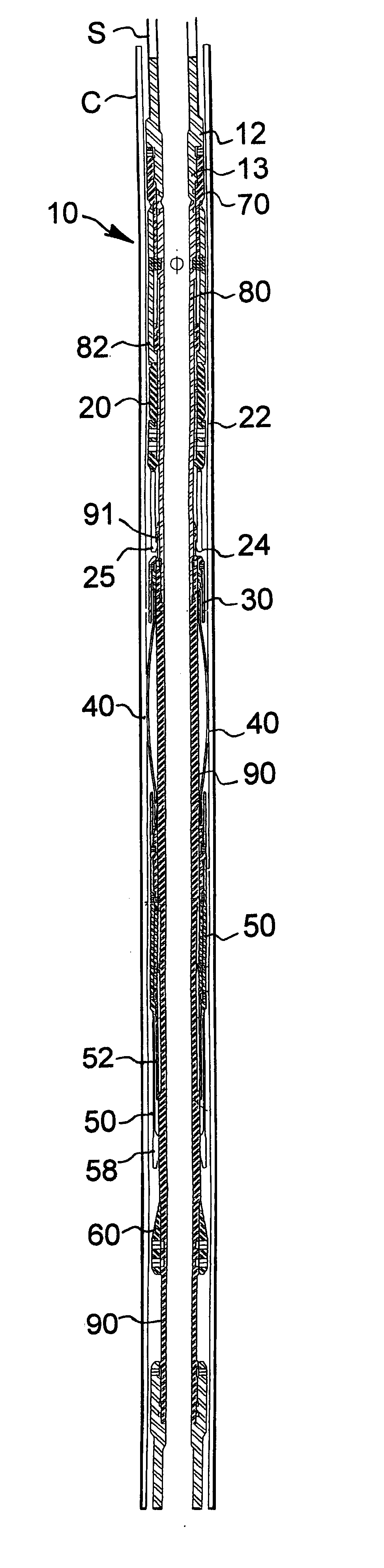
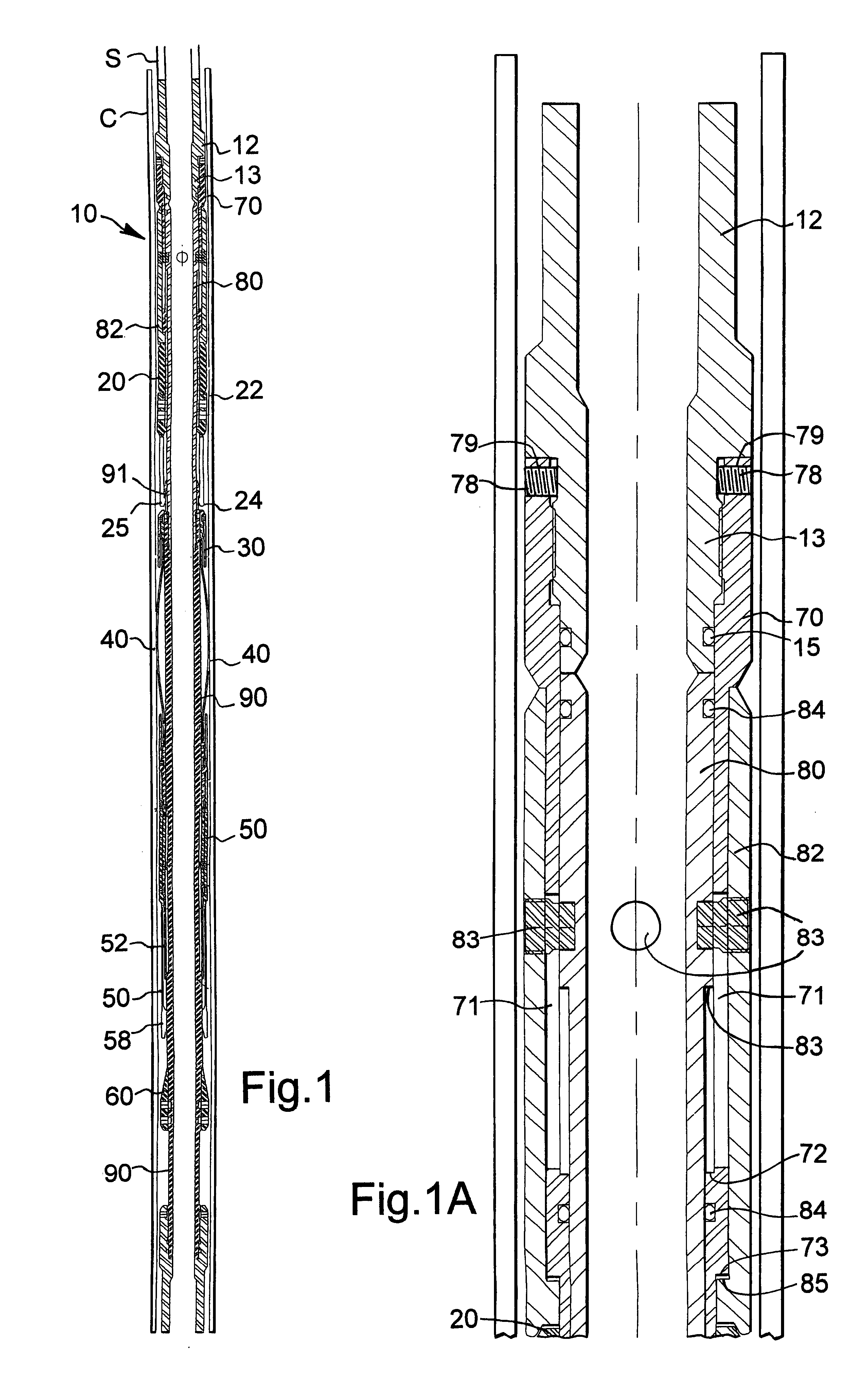
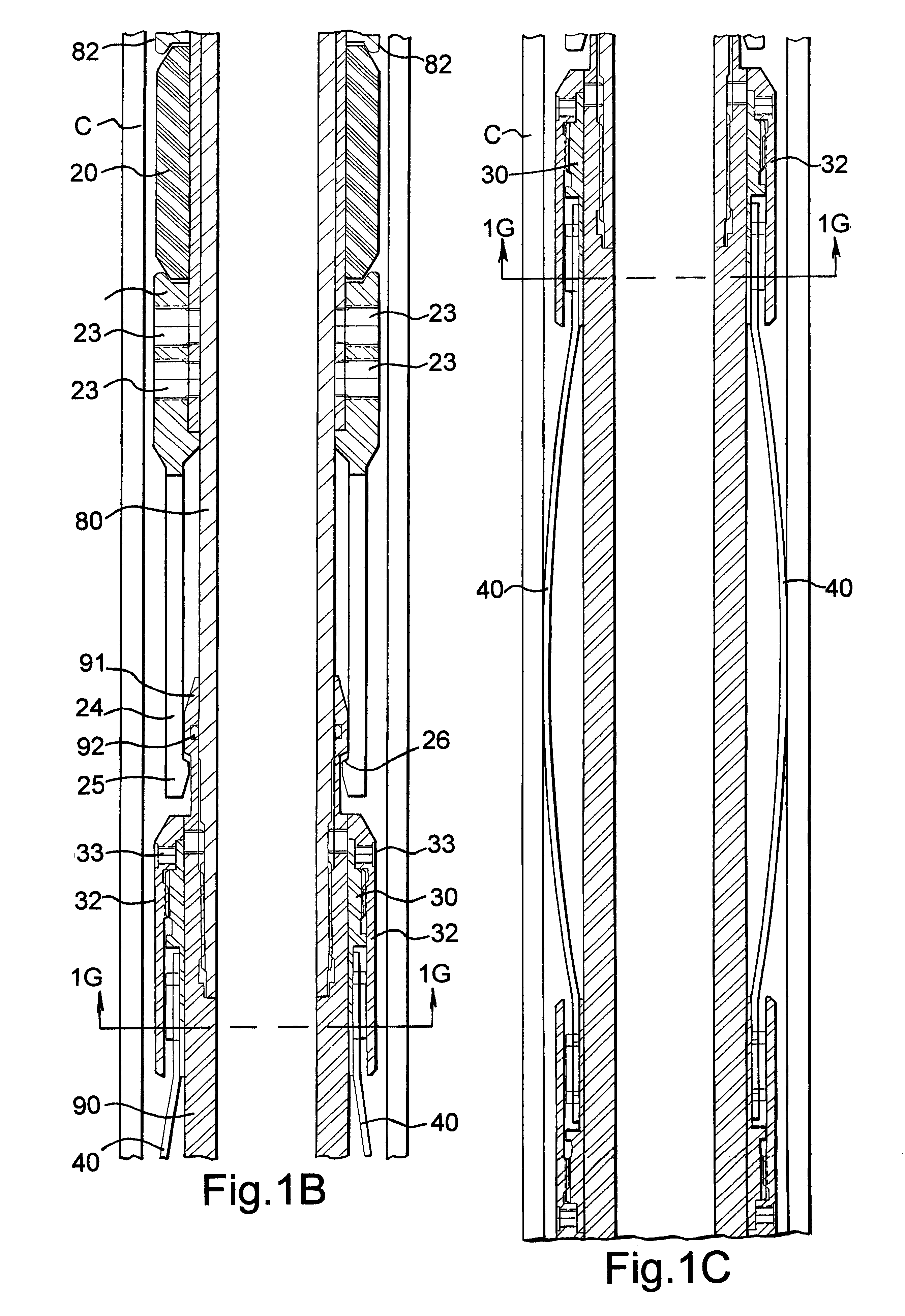
FIG. 1 shows a packer system 10 according to the present invention which has a top sub 12, a packer element 20, a packer element latch 22 drag springs 40, slip elements 50, a cone 60 and a bottom sub 14. FIGS. 1A-1F show enlargements of portions of the packer system 10 shown in FIG. 1. A system according to the present invention may be set within a tubular string (tubing or casing), within a gravel pack screen, within a packer, within a hanger flange, or within any wellbore device, system, tool, or apparatus with a suitable bore therethrough.

The top sub 12 has a lower end 13 to which is threadedly connected a pulling element mandrel 70. Set screws 78 through holes 79 hold the mandrel 70 in place. An o-ring 14 seals the top-sub-mandrel interface.

The mandrel 70 extends down between an upper body 80 and a support 82. Retainer screws 83 secure the upper body 80 and the support 82 together. These screws have a center portion that is movable within slots 71 in the mandrel 70, allowing the...


PUM


Abstract

A wellbore system with a tubular string extending from an earth surface down into a wellbore in the earth, a packer system with a selectively settable packer element, and a disconnect located between an end of the tubular string and the packer system, the disconnect operable from the surface by imposing a downward force on the tubular string. In one aspect the packer system's packer element is a tension-set packer element. A wellbore disconnect with a top sub, a piston having an upper end secured to the top sub and a portion below the upper end releasably secured with at least one releasable member to a carrier member, the carrier member having apparatus for selectively gripping the piston, the apparatus for selectively gripping the piston also selectively gripping a bottom sub within which the piston is movable, the at least one releasable member releasable in response to a downward force on the disconnect.

Description

1. Field of the InventionThis invention is related, among other things, to wellbore packer systems and, in certain aspects, a tension-set packer run on coil tubing. In other aspects, a set-down disconnect is used with such a system.2. Description of Related ArtCoil tubing cannot be rotated. Certain prior art down-hole tools that require rotation cannot be used with coil tubing. Consequently, hydraulically set packers are used with coil tubing. Coil tubing can be reciprocated. One prior art patent, U.S. Pat. No. 5,095,979 provides apparatus that operates in well production tubing by reciprocating the coil tubing. The apparatus has a pin moving in a groove that allows a packer to be run into production tubing, set, and released by the longitudinal movement of no coil tubing only.In certain prior art wellbore operations in which fluid with solids is being pumped into the wellbore (e.g. sand, proppant, or other solids), a ball actuated disconnect may be ineffective. In such situations a...

Claims


Application Information

Patent Timeline
Patent Type & Authority Patents(United States)
IPC IPC(8): E21B17/02E21B17/06E21B17/00E21B23/06E21B23/00E21B17/10
CPCE21B17/06E21B23/06E21B23/006E21B17/1014
Inventor HAUGEN, DAVID MICHAELINGRAM, GARY DURONHOFFMAN, COREY EUGENEBEEMAN, ROBERT STEPHEN
Owner WEATHERFORD TECH HLDG LLC
Why Eureka
Try Eureka