Detachable rail for a drawer track

a technology of drawer track and detachable rail, which is applied in the field of detachable rail for drawer track, can solve the problems of drawer often rebounds and extends, his fingers are easily injured, and are not very convenien

Inactive Publication Date: 2001-07-10
YANG JUN LONG
View PDF7 Cites 61 Cited by
  • Summary
  • Abstract
  • Description
  • Claims
  • Application Information

AI Technical Summary

Problems solved by technology

1. It presents a safety hazard. Whatever a user wants to push the drawer back or detach the drawer, he must press the lever (93) of the retaining plate (90). However, the retaining plate (90) always is a thin metal plate and formed by molding so the edge is very rough and sharp like a knife. Consequently, if a user is careless when pressing the retaining plate (90), his fingers are easily injured.
2. It is not very convenient. The conventional retaining device track (60) only has a limit notch (66) formed on one end. Consequently, the drawer often rebounds and extends again for some reason after being pushed in. It is not very convenient and sometimes a user may bump or hit the extended drawer.

Method used


Image

  • Detachable rail for a drawer track
  • Detachable rail for a drawer track
  • Detachable rail for a drawer track

Examples


Embodiment Construction

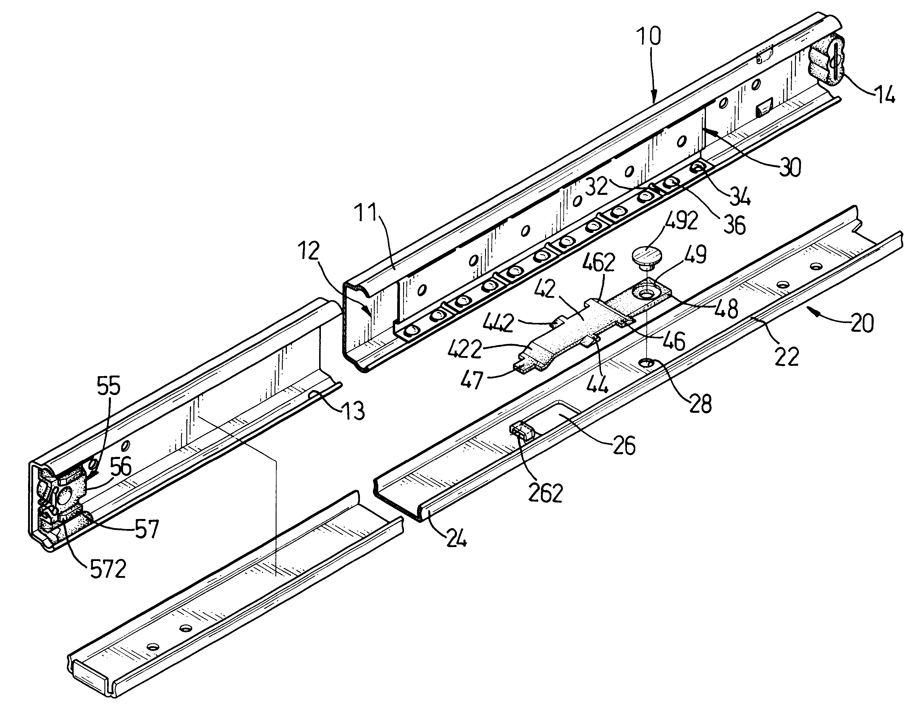
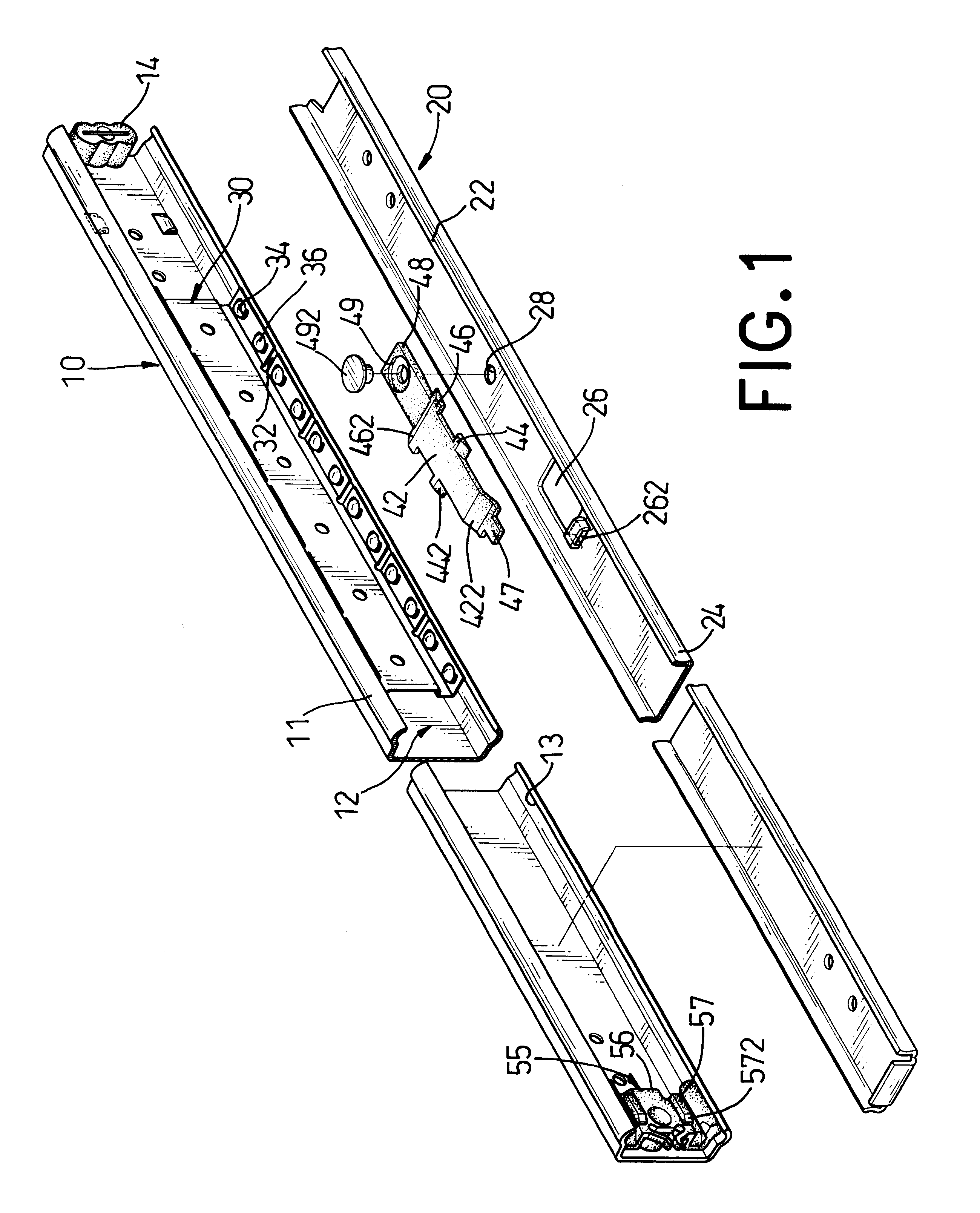
With reference to FIG. 1 and FIG. 2, the detachable rail for a drawer track in accordance with the present invention essentially comprises: a track (10), a bearing (30), a rail (20) and a limit device (40). The bearing (30) is slidably mounted in the track (10). The rail (20) is slidably mounted in the bearing (30) such that the rail (20) can slide in the track (10) and is limited to one longitudinal end of the track (10). The limit device (40) is fixedly attached to the rail (20) and is located between the rail (20) and the track (10).

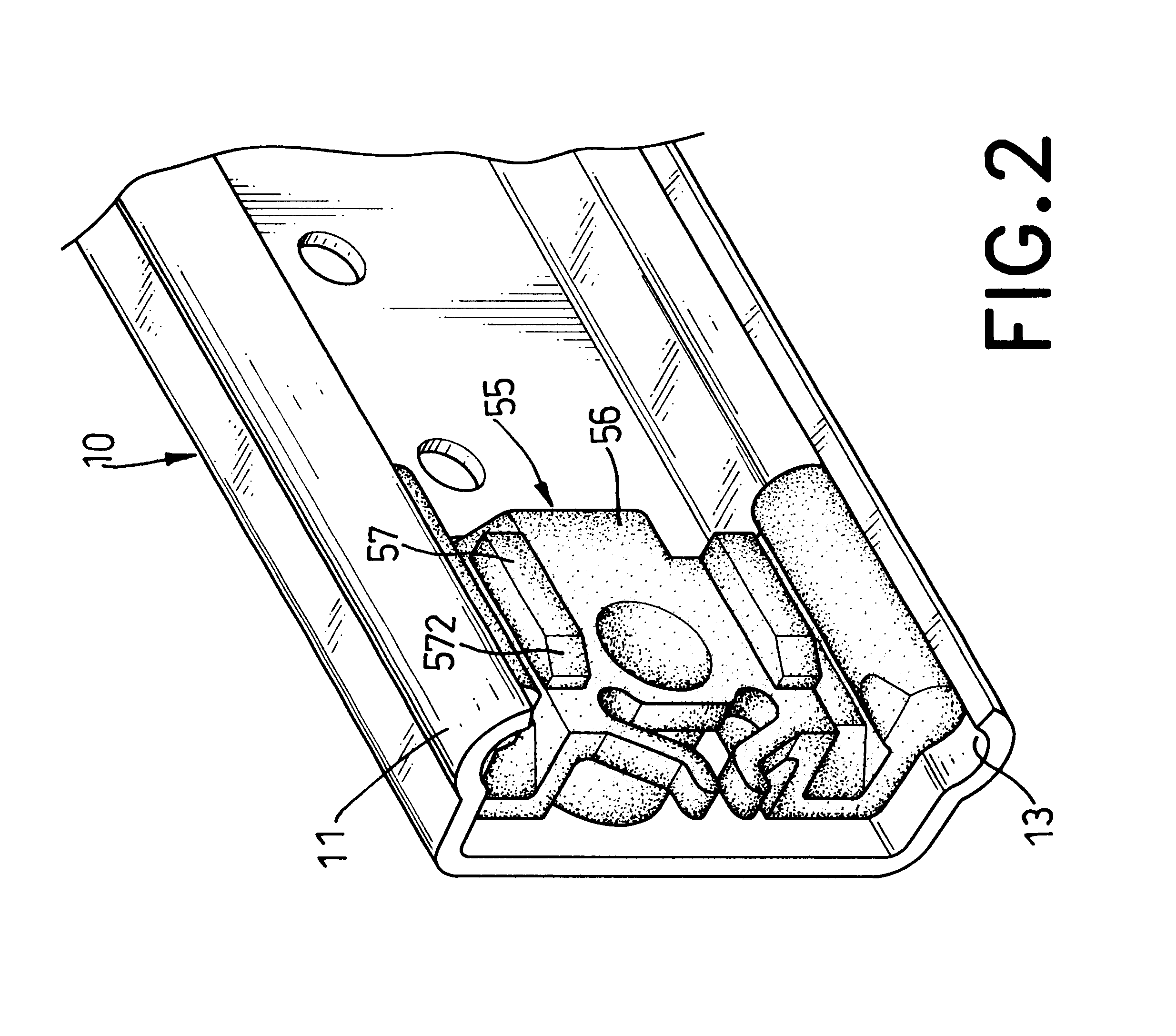
The track (10) contains a slide wall (11) integrally extending from each side so that a sliding area (12) is formed between the slide walls (11). Each slide wall (11) has a guide (13) extending from the edge of the slide wall (11). A limit plate (14) is located at one end of the sliding area (12), and a limit block (55) is located at the other end of the sliding area (12).

The bearing (30) is essentially U-shaped and has a set of races (32) on the legs...


PUM


Abstract

A detachable rail for a drawer track which essentially comprises a track and a rail is disclosed. By means of the limit block fixedly attached to the track and the limit device fixedly attached to the rail, it is very easy to detach the rail from and attach the rail to the track of a drawer.

Description

1. Field of the InventionThe present invention relates to a detachable rail for a drawer track, more particularly, to a detachable drawer rail that comprises suitable means to facilitate removing and installing the rail on a drawer track.2. Description of Related ArtWith reference to FIGS. 7 and 8, a conventional retaining device for a drawer track in accordance with the prior comprises a track (60), a rail (70) slidably mounted in the track (60) and a retaining plate (90) attached to the rail (70). The conventional track further comprises a bearing (80) mounted between the track (60) and the rail (70) to make the rail (70) slide more easily in the track (60).The track (60) is U-shaped and has two sidewalls (61) with a guide (63) defined in each sidewall (61). A guide (63) is formed on each sidewall (61). A limit notch (66) is formed on one end of the track (60), and a limit plate (64) extends perpendicular to the track (60) on the other end. The track (60) has multiple holes (65) d...

Claims


Application Information

Patent Timeline
Patent Type & Authority Patents(United States)
IPC IPC(8): A47B88/04A61B3/024A61B3/02A61B5/16A61B5/18
CPCA47B88/14A47B88/57A47B2088/4235A47B88/487
Inventor YANG, JUN-LONG
Owner YANG JUN LONG
Why Eureka
Try Eureka