Hinge with a safety shield plate unit

a safety shield plate and hinge cover technology, applied in the field of hinges, can solve the problems of obstructing the operation of taking out an article, and the hinge cover c is rather costly

Inactive Publication Date: 2001-10-30
SUGATSUNE IND CO LTD
View PDF6 Cites 31 Cited by
  • Summary
  • Abstract
  • Description
  • Claims
  • Application Information

AI Technical Summary

Problems solved by technology

Such a hinge cover C limits the space available for storing goods in the furniture and can obstruct the operation of taking out an article from and putting it back into the furniture, although the hinge cover C is rather costly.
Additionally, such a safety shield plate unit will not be expensive but will be sized relatively small so that it will not reduce the available space of the furniture to which it is fitted.

Method used


Image

  • Hinge with a safety shield plate unit
  • Hinge with a safety shield plate unit
  • Hinge with a safety shield plate unit

Examples


Embodiment Construction

Now, the present invention will be described by referring to the accompanying drawings that illustrate preferred embodiments of the invention.

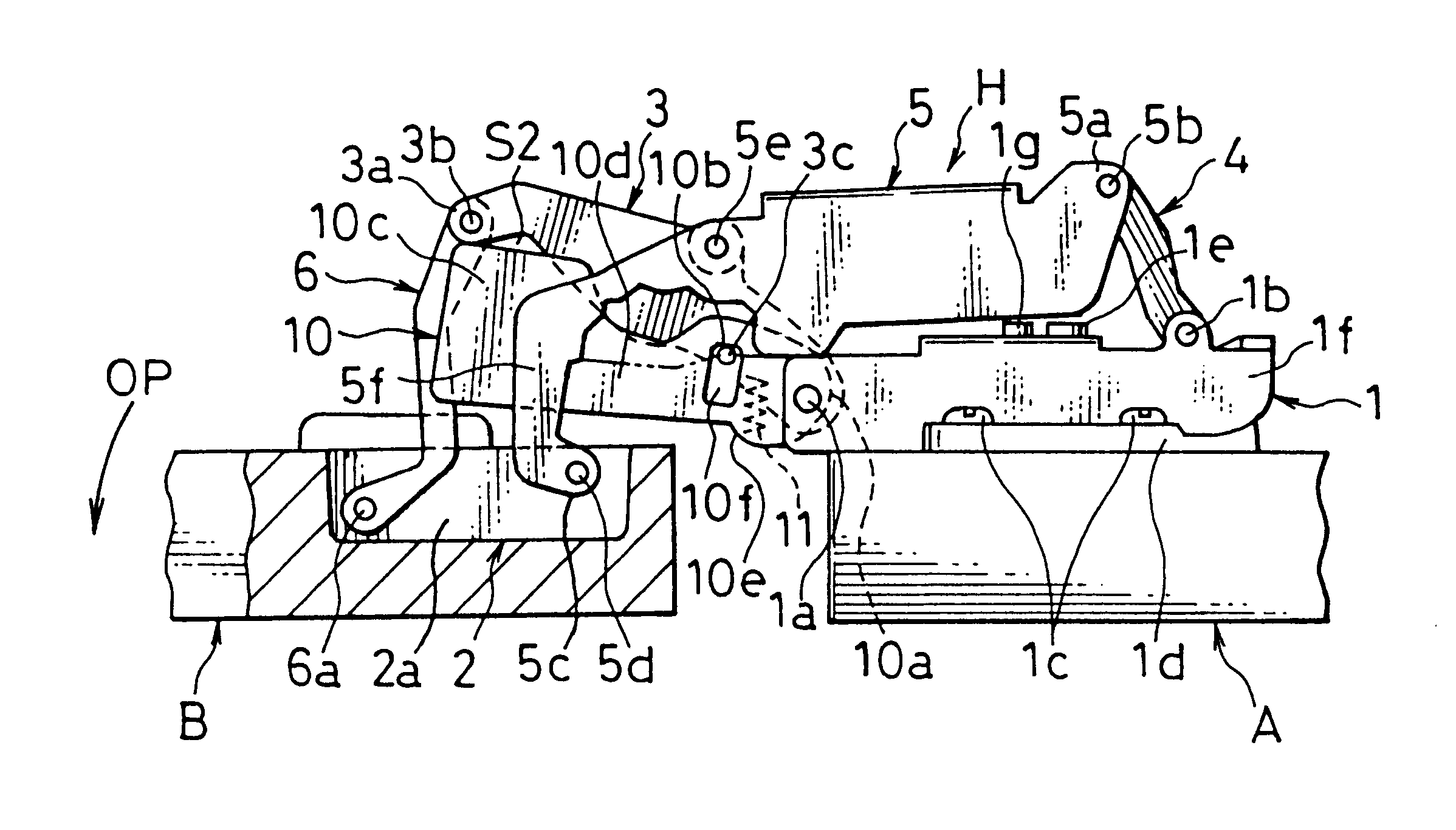
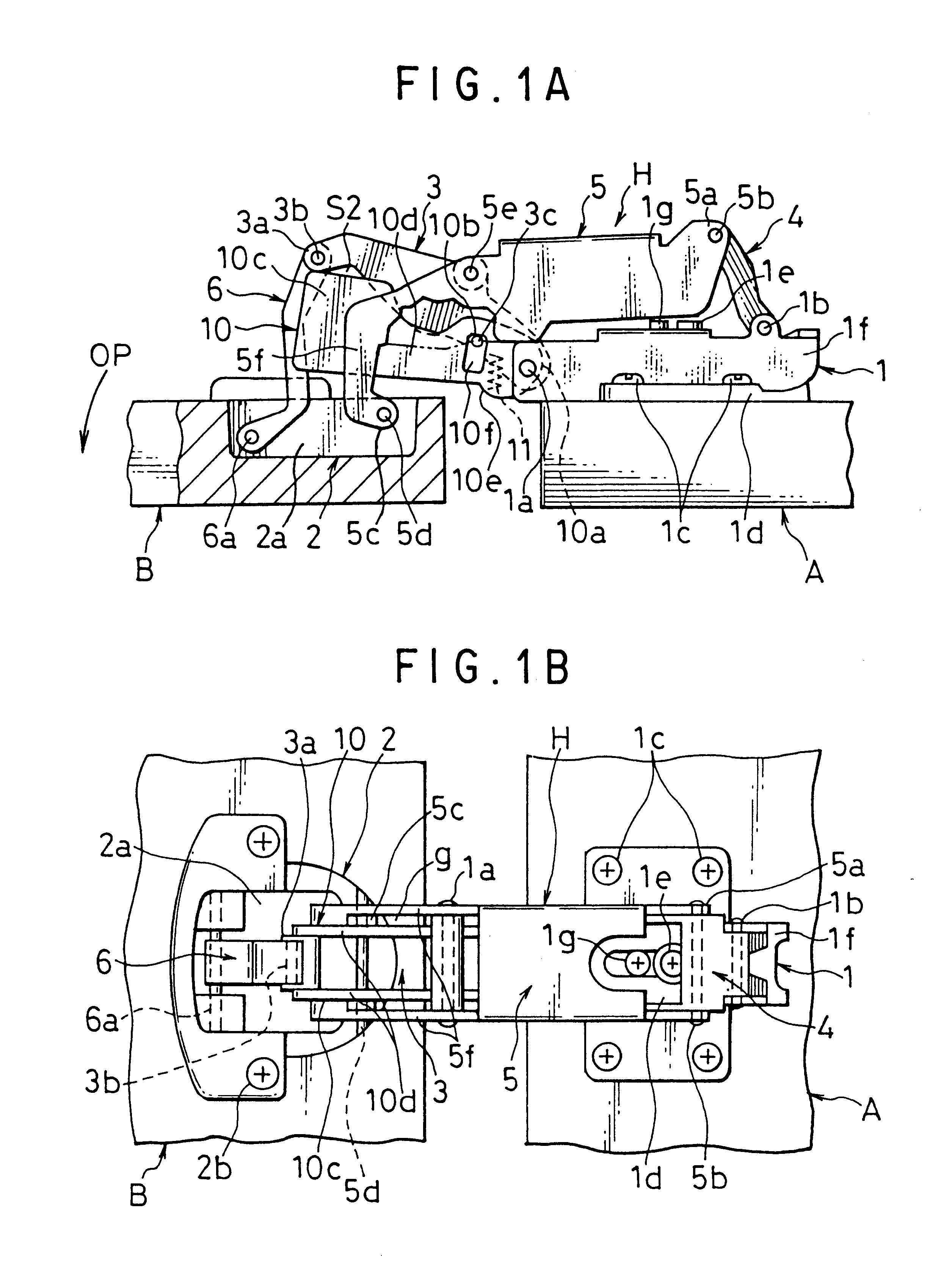
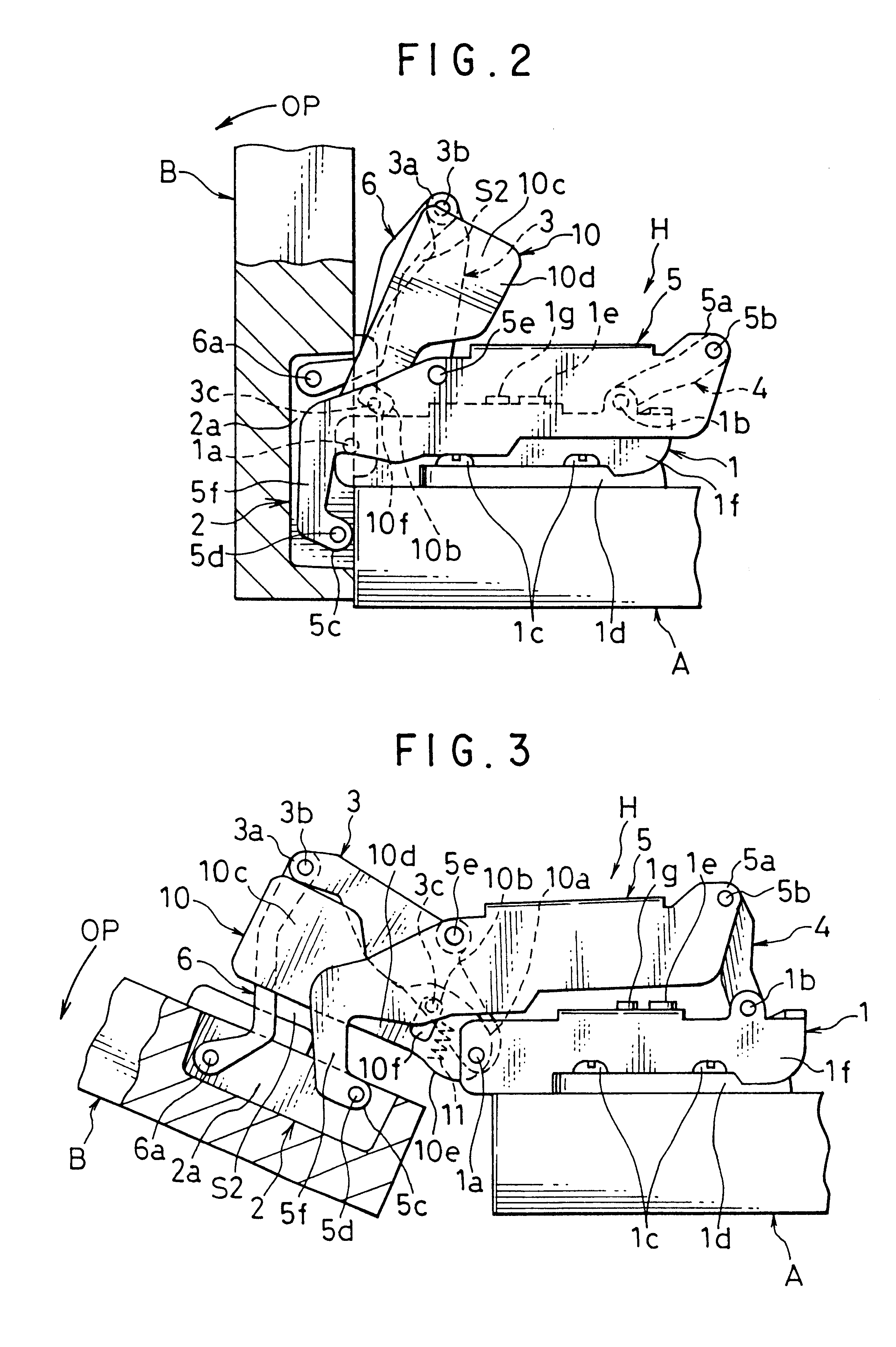
FIGS. 1 through 5 schematically illustrate preferred embodiments according to the first aspect of the invention. Referring to FIGS. 1 through 5, hinge main body H is used to link a fixed plate A and a movable plate B and has a configuration substantially identical with that of the known hinge illustrated in FIGS. 14 through 16. Therefore, the components which are the same as the counterparts of the known hinge are denoted respectively by the same reference symbols and will not be described any further unless some additional description is deemed to be necessary.

The hinge comprises a fixing member 1, a cup-shaped fixing member 2, a movable link arm 3 for linking the fixing member 1 and the cup-shaped fixing member 2, a movable rear arm 4, a movable intermediary arm 5 and a movable front arm 6, which are rotatably linked together by means of a f...


PUM


Abstract

A hinge with a safety shield plate unit is designed not to cover the hinge but to be rotatably fitted to the fixed front shaft of the hinge and be resiliently urged toward the cup-shaped fixing member of the hinge by a resilient member in such a way that the safety shield plate unit is prevented from unnecessarily moving toward the cup-shaped fixing member by causing the anchoring sections of the movable link arm to abut the respective anchored sections of the safety shield plate unit. The hinge main body includes a fixing member fitted to a fixed plate and a cup-shaped fixing member fitted to a movable plate. The members are linked together by movable arms. A safety shield plate unit fitted to the fixed front shaft linking the fixing member and the movable link arm is urged downward to follow and hide the hazardous area defined by the movable arms and the cup-shaped fixing member and having a volume that increases with the opening movement of the movable plate. The anchored sections of the safety shield plate unit are held by the respective anchoring sections to prevent the safety shield plate unit from inadvertently falling into the cup-shaped space and blocking the opening movement of the hinge.

Description

1. Field of the InventionThis invention relates to a hinge to be used to allow a furniture door to swing open and closed. More particularly, it relates to a hinge comprising a plurality of movable arms and a safety shield plate unit adapted to prevent part of the clothes or a finger of the user that is inadvertently put into the hazardous space with a variable volume defined by the moving arms of the hinge from being damaged or, in the worst case, cut by the moving arms.2. Prior ArtThere are known hinges designed to prevent part of the clothes or a finger of the user that is inadvertently put into the hazardous space with a variable volume defined by the moving arms of the hinge from being damaged.FIGS. 14 through 16 of the accompanying drawings schematically illustrate a known hinge of the type under consideration (Japanese Utility Model Publication No. 5-2287). It comprises a fixing member 1 to be rigidly fitted to the inside surface of an anchor plate A, which may be a lateral pl...

Claims


Application Information

Patent Timeline
Patent Type & Authority Patents(United States)
IPC IPC(8): E05D3/00E05D11/00E05D3/06E05F7/00
CPCE05D3/16E05D11/0054E05D2003/166Y10T16/5476Y10T16/547Y10T16/533E05Y2900/20
Inventor KOSHIKAWA, SHINICHIROU
Owner SUGATSUNE IND CO LTD
Why Eureka
Try Eureka