Dual strap system for conversion of bags to backpacks

a dual strap and backpack technology, applied in the field of strap systems, can solve the problems of insufficiently meeting the requirements of several computer cases, unable to disclose the unique features of prior art devices, and unable to meet the requirements of easy removal from the carrying case, and unable to meet the requirements of weather and impact protection,

Inactive Publication Date: 2001-11-06
JOHNSON JUSTIN
View PDF7 Cites 77 Cited by
  • Summary
  • Abstract
  • Description
  • Claims
  • Application Information

AI Technical Summary

Problems solved by technology

However, none of the prior art devices disclose the unique features of the present invention.
(Unfortunately, as these microcomputers become more powerful tools for scientists, students, engineers, artists, and medical personnel, there is an ever greater need to protect these devices while enhancing their ready access and ease of use.
These two conflicting requirements, easy removal from the carrying case, and superior protection from weather and impact, have not been adequately met by these several computer cases.

Method used


Image

  • Dual strap system for conversion of bags to backpacks
  • Dual strap system for conversion of bags to backpacks
  • Dual strap system for conversion of bags to backpacks

Examples


first embodiment

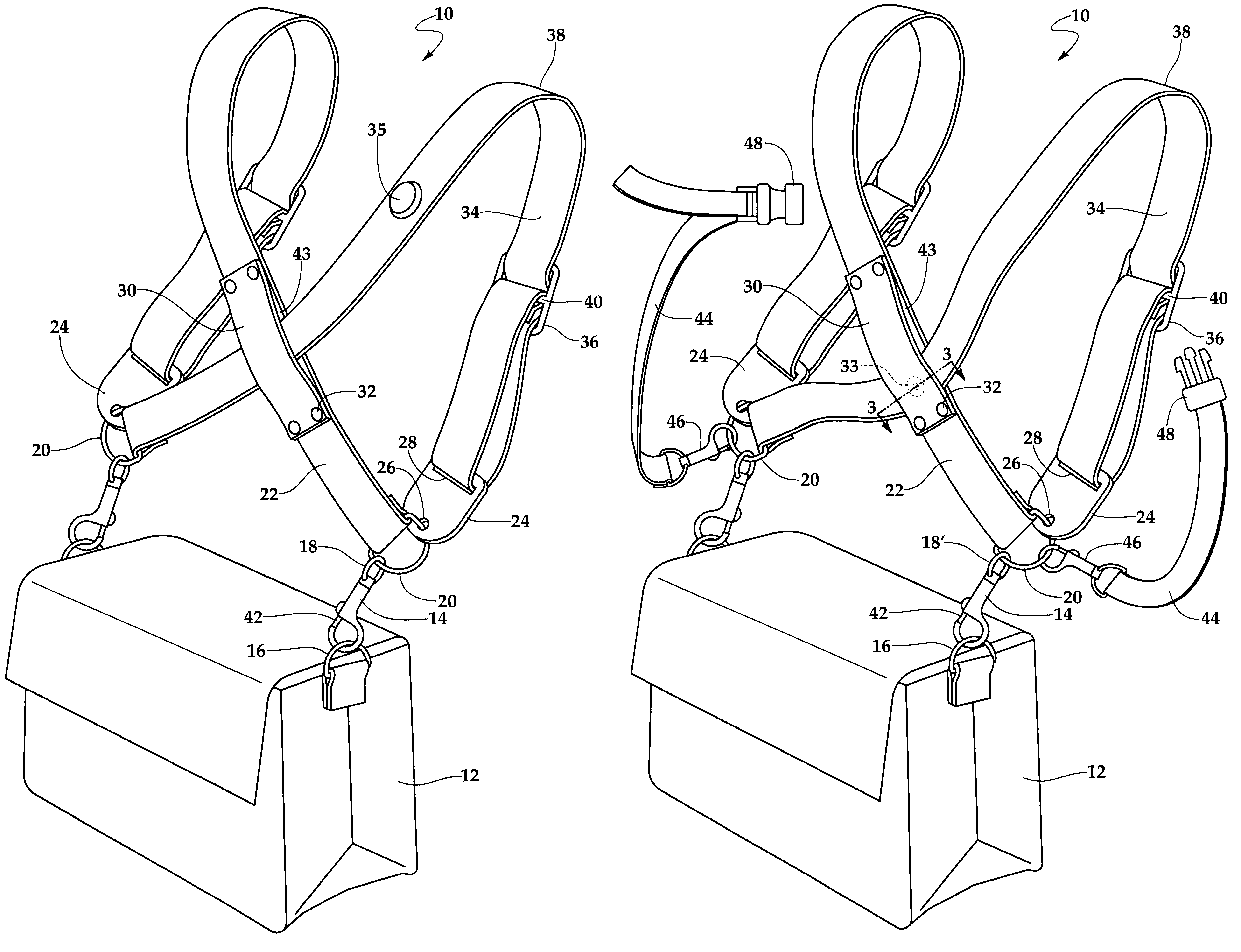
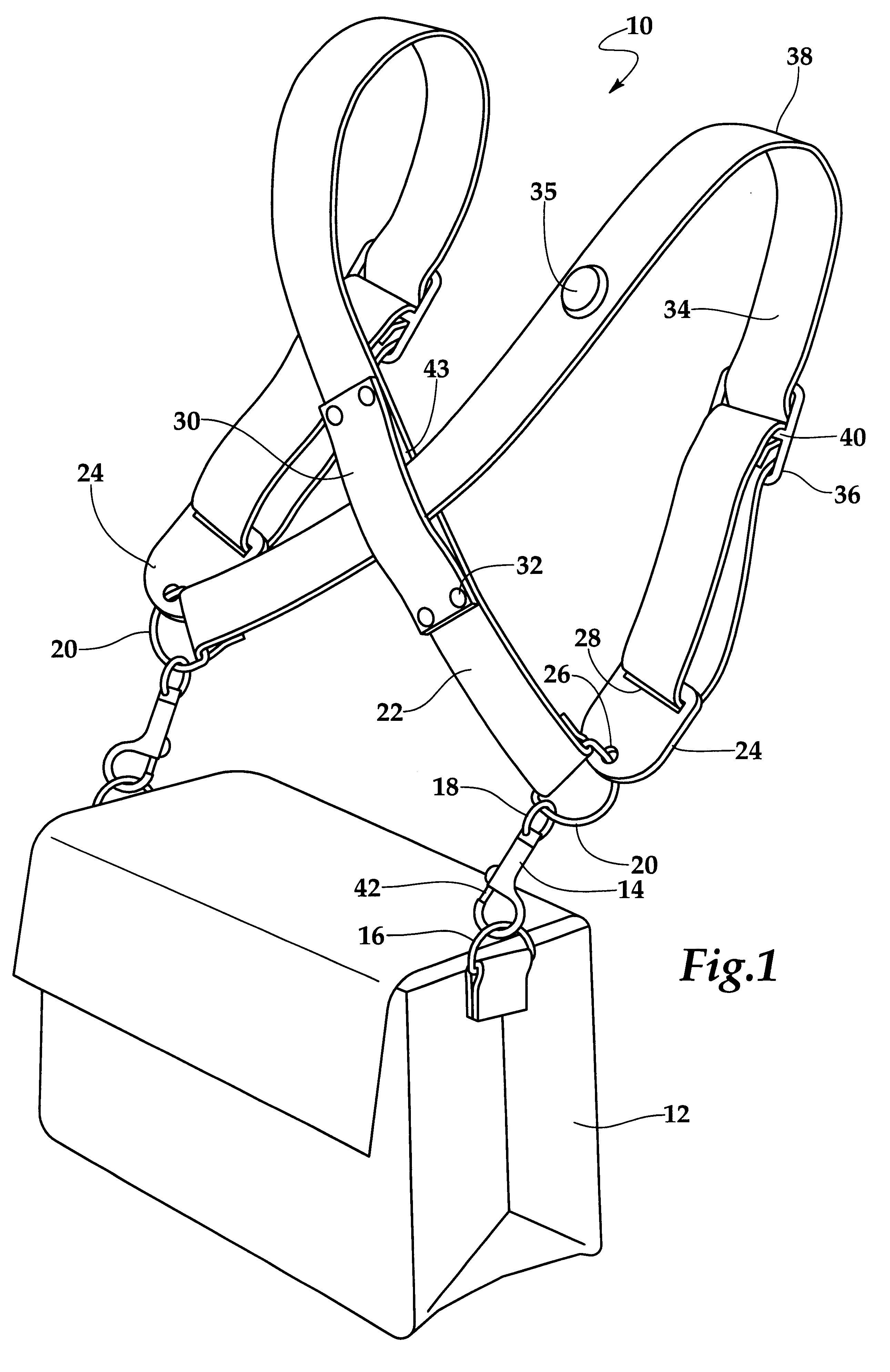
Turning to FIG. 1, therein is shown a perspective view of the present invention 10. Shown therein is the utility bag 12; i.e., a computer bag, having connected thereto the present invention 10 by use of a pair of clip means 14 which are in turn connected to a pair of connection means 16 on the bag 12. The clips 14 have a means for connection on the opposite end of the clip which are a fixed round loop 18 which are situated in a perpendicular plane to the clip member 14. Clip 14 is a safety clip having a spring loaded slidable member 42 which keeps the clip 14 secured in place. The fixed loop 18 is connected to a D loop 20 which is attached to one end of strap member 22 and having attached to the other end of strap 22 another fastener or plate 24. Plate 24 is a solid member having an aperture 26 therein for receiving the D loop 20 and having a slot 28 therein for a belt end which belt end is threaded through slot 28 and is then folded back upon itself and sewn in place. Belt 22 has a...

second embodiment

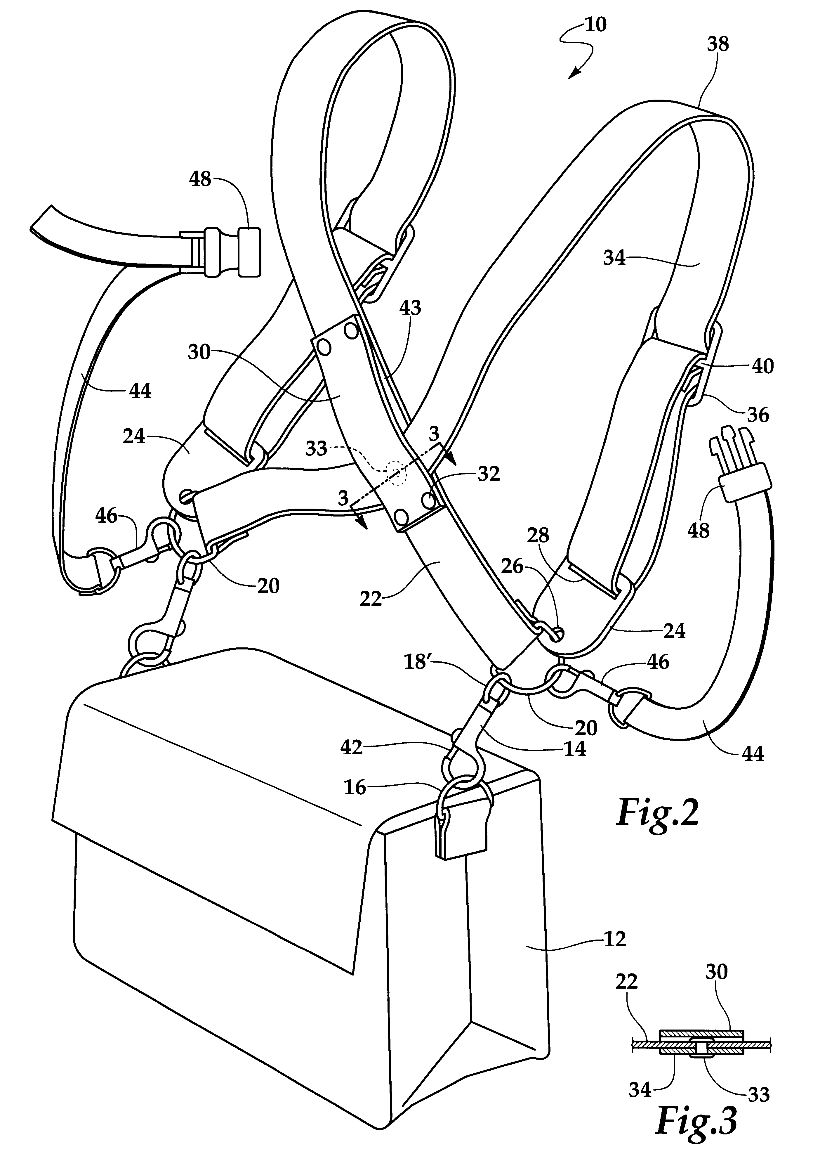
In operation, when the present invention 10 is to be placed on the back of the user, the user faces toward the straps and picks up strap 34 with his right hand at grab position 38 (production models will have the trademark of the present invention located at position 38 so that the user can easily know where to grab) and lifts upwardly which causes the rigid member 30, which acts as a cantilever-like member, to rotate downwardly about swivel means 33 to a generally horizontal position which creates a loop-like opening in strap 22; the user then puts his right arm and shoulder through strap 34 in the conventional manner and then puts his other arm through the loop created in strap 22 by the cantilever-like action of rigid member 30 in the conventional manner which then places the backpack centrally across the back of the user as the user shoulders the present invention. The swivel means 33 is positioned at a point on belt 22 about 25.8 percent of the total length of the belt as measu...


PUM


Abstract

The present invention discloses a dual strap system used for connection to a utility bag, such as a computer bag, by which the bag can be converted into a backpack, In a first embodiment, the dual straps of the system cross each other by means of a rigid member disposed at the crossing point to provide a twist resistant arrangement and properly center the present invention on the back of the user. One strap has a stop located thereon which helps position the straps with respect to the rigid member when the strap is off the bag and maintain the integrity of the device during the time the device is not installed on the bag. An attachment clip system is also provided which automatically positions the straps properly for use when the right hand grab technique is used to shoulder the device. Further, the clip system is designed to keep the straps from tangling when the device is off the bag. In a second embodiment, a swivel is provided for connection of the two straps which allows the rigid member to act as a cantilever-like member which helps provide a proper opening in the straps for shouldering the present invention.

Description

1. Field of the InventionThe present invention generally relates to strap systems for carrying utility bags manufactured with connection loops on the ends thereof, more particularly, is concerned with a dual strap system for converting utility bags to backpacks.2. Description of the Prior ArtStrap systems and backpacks have been described in the prior art. However, none of the prior art devices disclose the unique features of the present invention.In U.S. Pat. No. 5,429,288, dated Jul. 4, 1995, Sattler disclosed a supplemental carry strap for use with luggage, including golf bags, garment bags and the like, having a single shoulder carry strap including a padded or unpadded shoulder-contacting element having an optional positioning indicator and two connecting straps and to adjust the position of the carried luggage while retaining the shoulder element in the proper position for contacting the shoulder, and a coupling element for receiving the connecting straps and, further, having ...

Claims


Application Information

Patent Timeline
Patent Type & Authority Patents(United States)
IPC IPC(8): A45F3/14A45F3/04A45F3/00
CPCA45F3/04A45F3/14
Inventor JOHNSON, JUSTIN
Owner JOHNSON JUSTIN
Why Eureka
Try Eureka