Image developing device with sealing members for preventing toner leakage

Inactive Publication Date: 2002-01-01
BROTHER KOGYO KK
View PDF2 Cites 116 Cited by
  • Summary
  • Abstract
  • Description
  • Claims
  • Application Information

AI Technical Summary

Benefits of technology

will become more apparent

Problems solved by technology

This type of developing unit can leak toner.
The leaked toner can stain the interior of the image forming device and recording sheets, thereby degrading printing quality.
The leaked toner can also stain the user's hands or clothes during replacement of the developing unit.
The toner easily leaks from around the edges of the developing roller as the developing roller rotates.
However, with this configuration, toner can easily leak from between the layer thickness regulating blade and the side seals.
However, over a long period of use, fiber from the Teflon.TM. felt of the side seals can press up the pressing member and enter between the layer thickness regulating blade and the developing roller.
As a result, a gap can open between the pressing member and the developing roller.
That is, if the side seals press against the pressing member with a force sufficient for preventing t

Method used


Image

  • Image developing device with sealing members for preventing toner leakage
  • Image developing device with sealing members for preventing toner leakage
  • Image developing device with sealing members for preventing toner leakage

Examples


Embodiment Construction

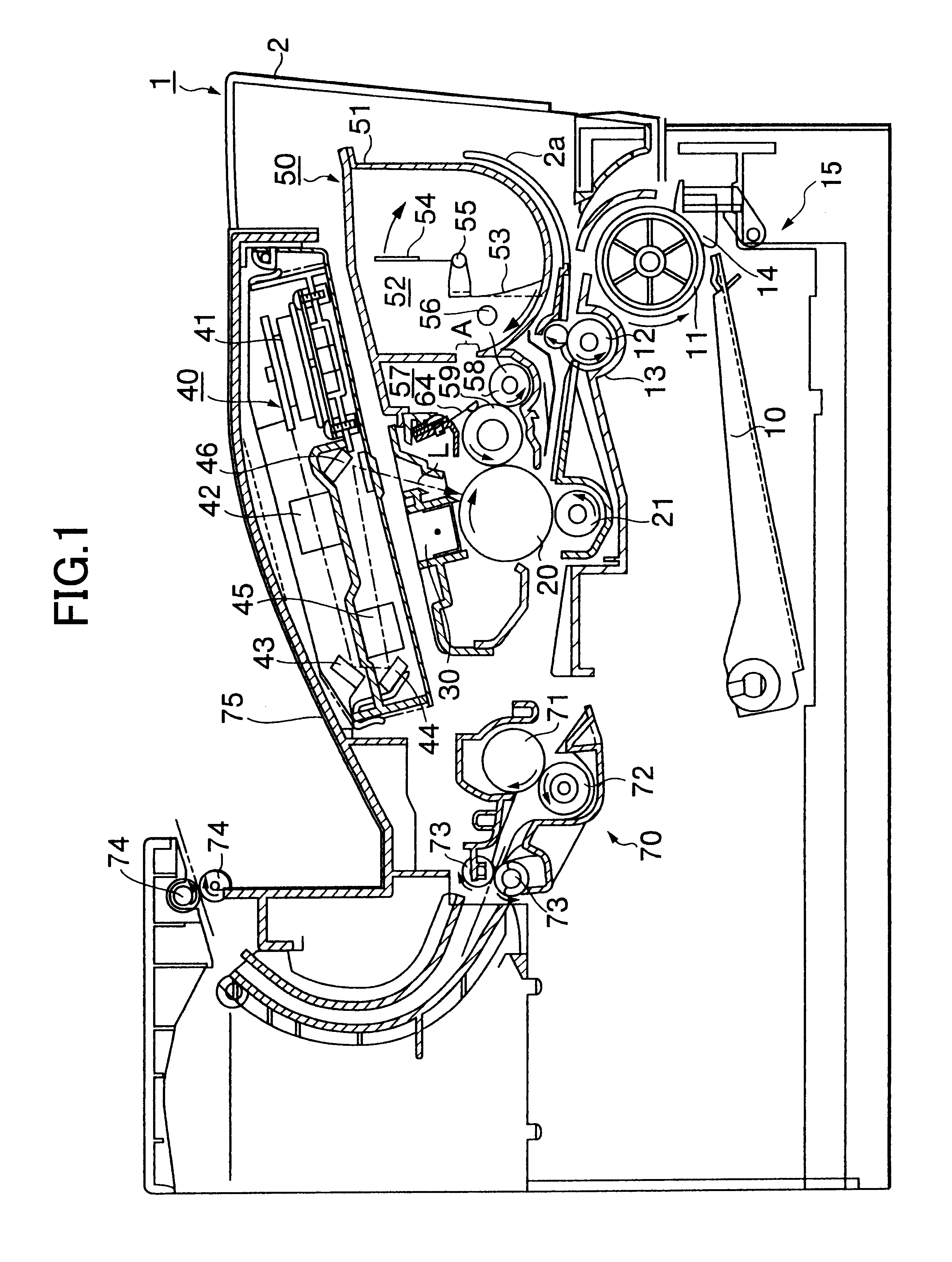
A laser beam printer 1 including a developing unit according to an embodiment of the present invention will be described while referring to the accompanying drawings.

As shown in FIG. 1, the laser beam printer 1 includes a case 2, a feeder unit 15 for supplying sheets (not shown) stored in a stack at the bottom portion of the case 2, a laser scanner unit 40, a developing unit 50, and various components aligned along a sheet transport pathway along which sheets are transported from the feeder unit 15 to be discharged from the pointer 1.

The feeder unit 15 includes a friction separation member 14, a sheet supply roller 11, and a sheet pressing plate 10. The sheet pressing plate 10 is pressed upward by a spring (not shown), and presses the sheets upward against the sheet supply roller 11. When the sheet supply roller 11 rotates in the direction indicated by an arrow in FIG. 1, the uppermost sheet of the stack in separated from between the sheet supply roller 11 and the friction separatio...


PUM


Abstract

A layer thickness regulating blade 64 has a plate spring 64b and a pressing number 64a fixed thereto. The plate spring 64b is formed longer than the pressing member 64a so that both ends of the plate spring 64b are exposed. A front surface resilient foam seal 112 made from sponge is attached to the exposed portions, in contact with sides of the pressing member 64a. Further, a Teflon(TM) film 113 is attached on the plate spring 64b so as to cover the front surface resilient foam seal 112. A sponge side seal 111 is adhered to the rear surface of the plate spring 64b. A sponge side seal 107 is adhered to the developing case 51 at a position that confronts the blade side seal 111. An end seal 106 is adhered across a step portion E of the developing case 51 and the upper end of the base seal 104, and can compressing deform with the blade side seal 111 and the upper side seal 107.

Description

1. Field of the InventionThe present invention relates to a developing unit, a process cartridge, and a developing cartridge for developing images using developing agent.2. Description of Related ArtA conventional image forming device includes a known developing unit that develops electrostatic latent images into visible images using charged particles of toner. This type of developing unit can leak toner. The leaked toner can stain the interior of the image forming device and recording sheets, thereby degrading printing quality. The leaked toner can also stain the user's hands or clothes during replacement of the developing unit.One such developing unit with this problem includes a developing roller and a layer thickness regulating blade. The developing roller transports toner on its surface, and the layer thickness regulating blade regulates the toner on the surface of the developing roller to a thin layer. The layer thickness regulating blade includes a stainless steel plate sprin...

Claims


Application Information

Patent Timeline
IPC IPC(8): G03G15/08
CPCG03G15/0817
Inventor SATO, FUMIKAZUDEGUCHI, HIDEAKIKAMIMURA, NAOYAHORINOE, MITSURU
Owner BROTHER KOGYO KK
Why Eureka
Try Eureka