Versatile pouring system including a funnel and spouts

a funnel and spout technology, applied in the field of funnels and pouring spouts, can solve the problems of preventing and affecting the flow of fluid and drainag

Inactive Publication Date: 2002-01-22
HOPKINS MFG
View PDF7 Cites 35 Cited by
  • Summary
  • Abstract
  • Description
  • Claims
  • Application Information

AI Technical Summary

Problems solved by technology

For example, purchasing an assortment of independent funnels and spouts of various sizes and shapes is an undesirable solution due to difficulty in storing the funnels and spouts in such a manner as to prevent individual funnels and spouts from being misplaced from the set.
Unfortunately, these prior art devices are typically narrowly adapted to particular containers or applications.
For example, an existing combination device has a funnel component with a round mouth and centered neck unsuited to securely receiving and supporting rectangular fluid containers, such as oil containers.
Such a blade arrangement poses undesirable injury hazards, particularly when cleaning the funnel after use, and presents an obstruction on the funnel's interior surface which can impede fluid flow and drainage.
Furthermore, existing combination devices are typically not as versatile as may be desired with regard to the independent functionality of each component and the number of possible useful sub-combinations.
An additional drawback of many existing devices is the lack of a cap for preventing undesirable loss of fluid or residue remaining in the funnel or spout.
Where a cap is included, a means of retaining the cap typically is not, and so the cap is often misplaced of lost.
Where a retaining mechanism is included, the cap is typically not held in an upright orientation, such that any fluid or residue remaining in the cap undesirably drips out.

Method used


Image

  • Versatile pouring system including a funnel and spouts
  • Versatile pouring system including a funnel and spouts
  • Versatile pouring system including a funnel and spouts

Examples


Embodiment Construction

, below.

A preferred embodiment of the present invention is described in detail below with reference to the attached drawing figures, wherein:

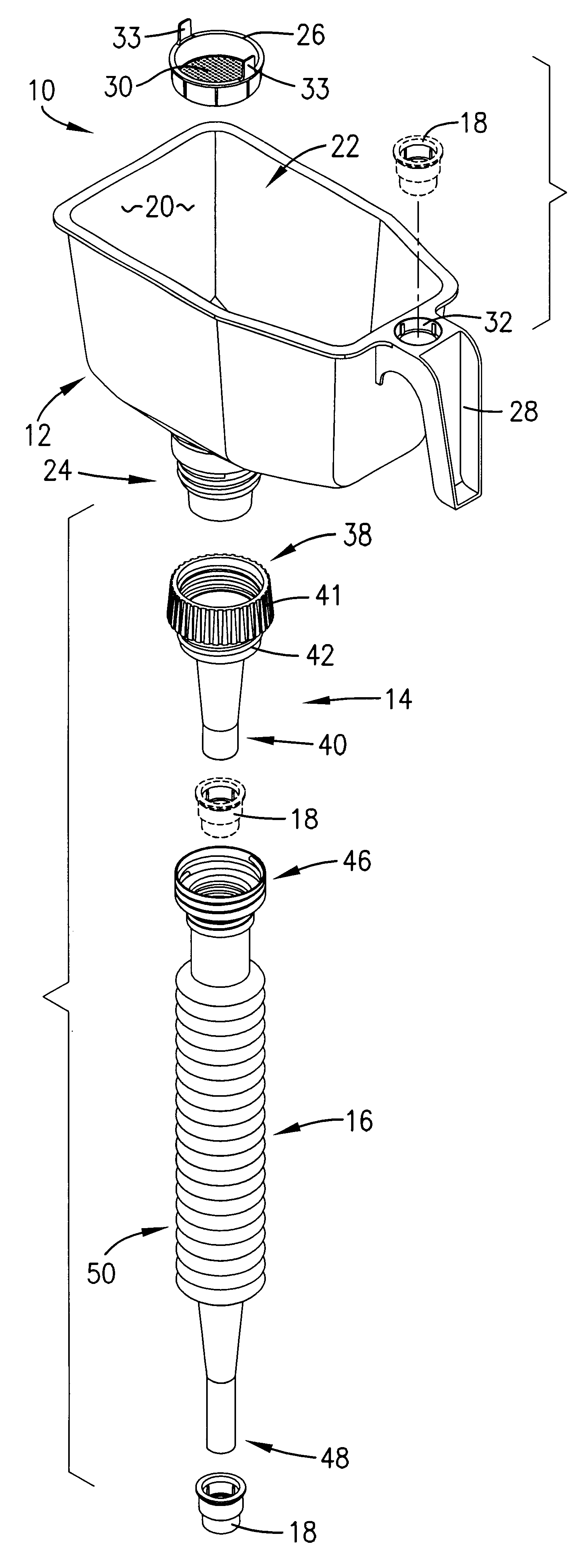
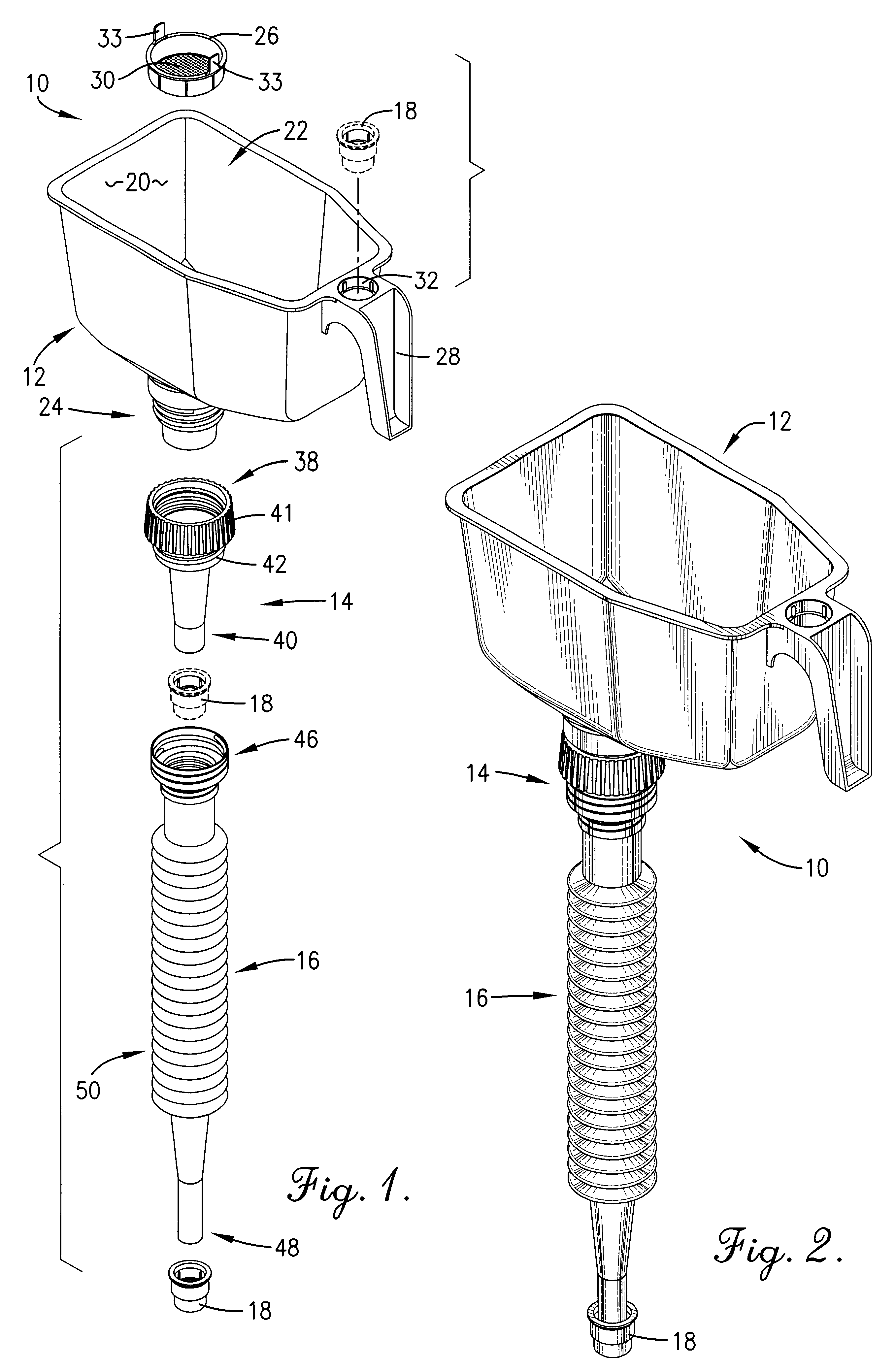
FIG. 1 is an exploded view of a preferred embodiment of the pouring system of the present invention, with alternative cap placements shown in broken line to facilitate understanding;

FIG. 2 is an isometric view of the assembled pouring system;

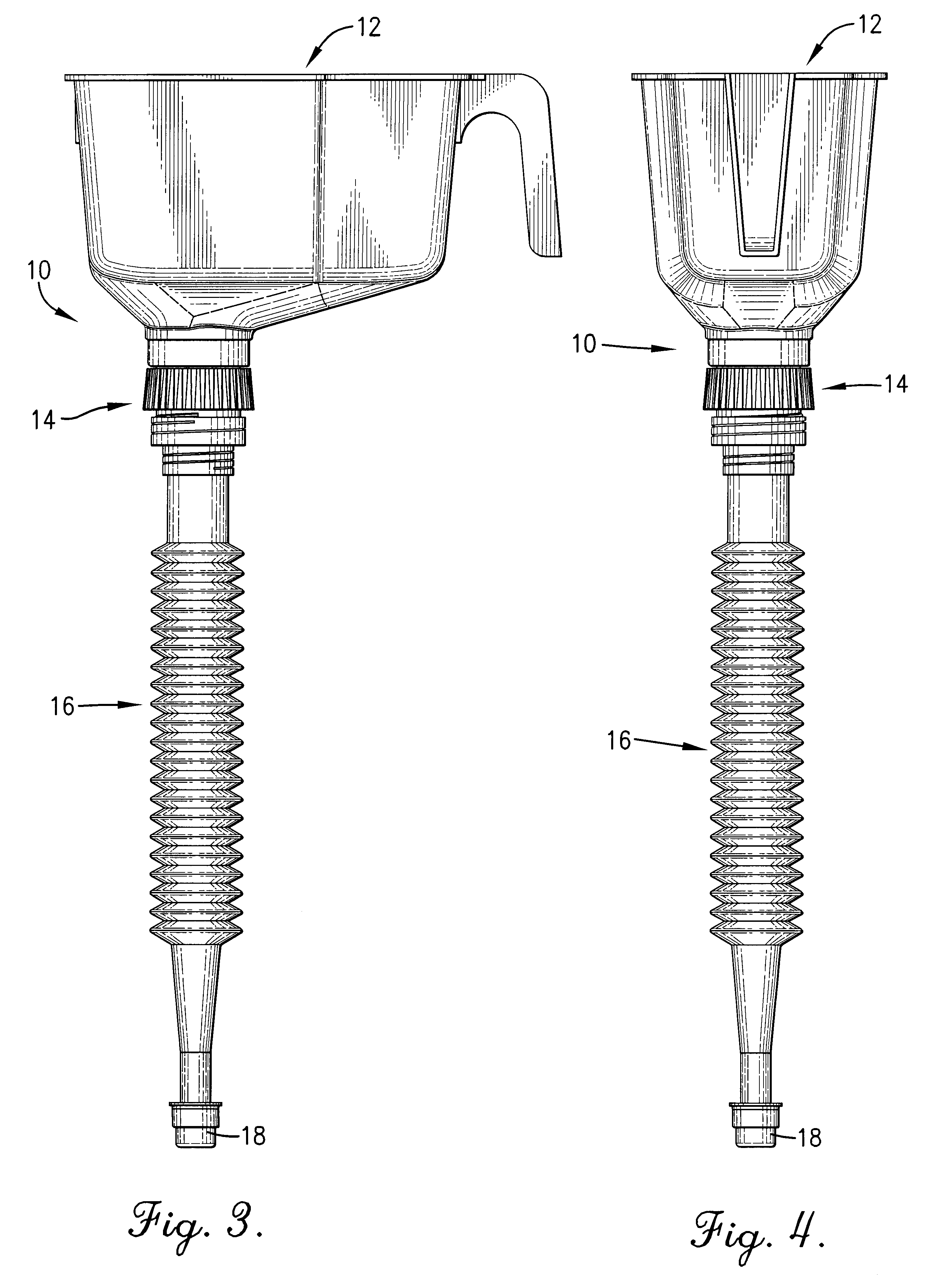
FIG. 3 is a right side elevational view of a preferred embodiment of the pouring system of the present invention;

FIG. 4 is a rear elevational view of the pouring system of FIG. 3;

FIG. 5 is a front elevational view of the pouring system of FIG. 3;

FIG. 6 is a top plan view of the pouring system of FIG. 3;

FIG. 7 is a bottom plan view of the pouring system of FIG. 3; and

FIG. 8 is a fragmentary right side sectional view taken along line 8--8 of FIG. 6, with alternative cap placements shown in broken line to facilitate understanding.

DETAILED DESCRIPTION OF A PREFERRED EMBODIMENT

Referring to FIGS. 1 and 8, a versa...


PUM


Abstract

A versatile pouring system (10) reducible to constituent components having independent and combinatorial functionality. The pouring system (10) comprises a funnel (12), including a removable filter (26); a first spout (14); a second spout (16); and a cap (18). The funnel (12) is semi-rectangular with an offset neck (24) to securely receive and support common one quart fluid containers. The removable filter (26) is operatively positioned within the funnel neck (24) to trap and retain residue or debris. The spouts (14, 16) are of different lengths and are coupleable with the funnel (12), with one another, or with common wide or small-mouthed fluid containers. The cap (18) fits both spouts (14, 16). All four constituent components can be assembled into a single coherent unit for convenient storage.

Description

1. Field of the InventionThe present invention relates to funnels and pouring spouts. More particularly, the invention relates to a versatile pouring system providing a wide variety of funnel and spout configurations and functions while unifying into an aggregate whole for convenient storage.2. Description of the Prior ArtIt is often desirable, particularly by professional and amateur mechanics, to have available a selection of funnels and pouring spouts so that the most suitable pouring means may be used for a particular job. It is further desirable, in order to facilitate storage and transportation, that these funnels and pouring spouts be combinable into as unified a package as may be possible and practical. For example, purchasing an assortment of independent funnels and spouts of various sizes and shapes is an undesirable solution due to difficulty in storing the funnels and spouts in such a manner as to prevent individual funnels and spouts from being misplaced from the set.Co...

Claims


Application Information

Patent Timeline
Patent Type & Authority Patents(United States)
IPC IPC(8): B67C3/00
CPCB67C11/02B67C2011/20
Inventor INGRAM, VICKI
Owner HOPKINS MFG
Why Eureka
Try Eureka