Sliding glass door track engagement and method

a technology of sliding glass doors and track engagement, applied in the field of sliding glass doors, can solve the problems of relatively unsightly rear angle 11 of the retainer

Inactive Publication Date: 2002-08-20
PGT INDS
View PDF11 Cites 30 Cited by
  • Summary
  • Abstract
  • Description
  • Claims
  • Application Information

AI Technical Summary

Problems solved by technology

The retainer angles 11 are relatively unsightly, and can be tripp...

Method used


Image

  • Sliding glass door track engagement and method
  • Sliding glass door track engagement and method
  • Sliding glass door track engagement and method

Examples


Embodiment Construction

Further objects and advantages of the present invention will be best understood in conjunction with the accompanying illustrative drawings in which:

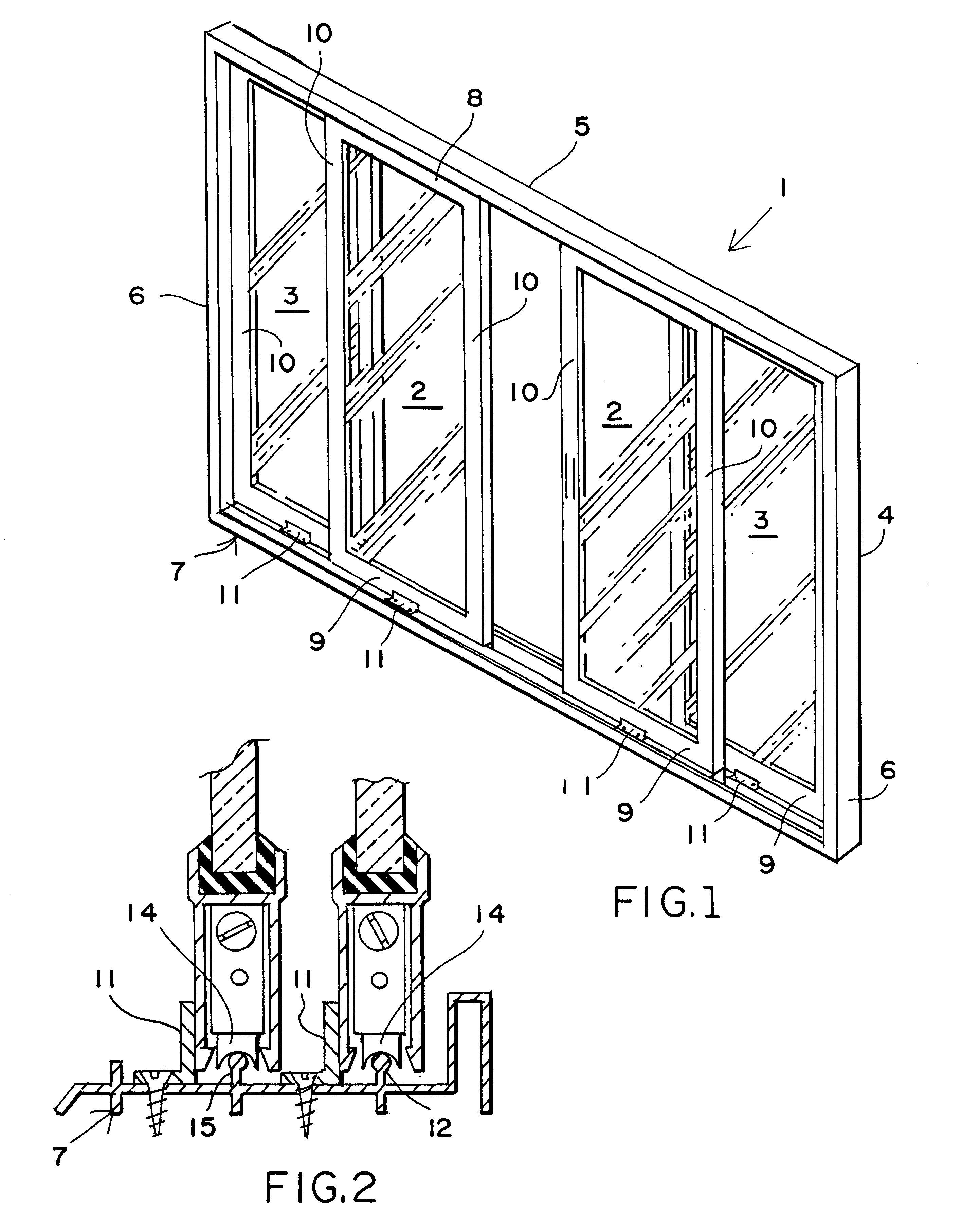
FIG. 1 is an isometric view of an illustrative sliding glass door assembly having two central moveable panels flanked by end fixed panels;

FIG. 2 is a cross-section showing the configuration of the two panels and how a retainer angle has been employed in the prior art to assist in reducing the tendency of the panel to jump the track;

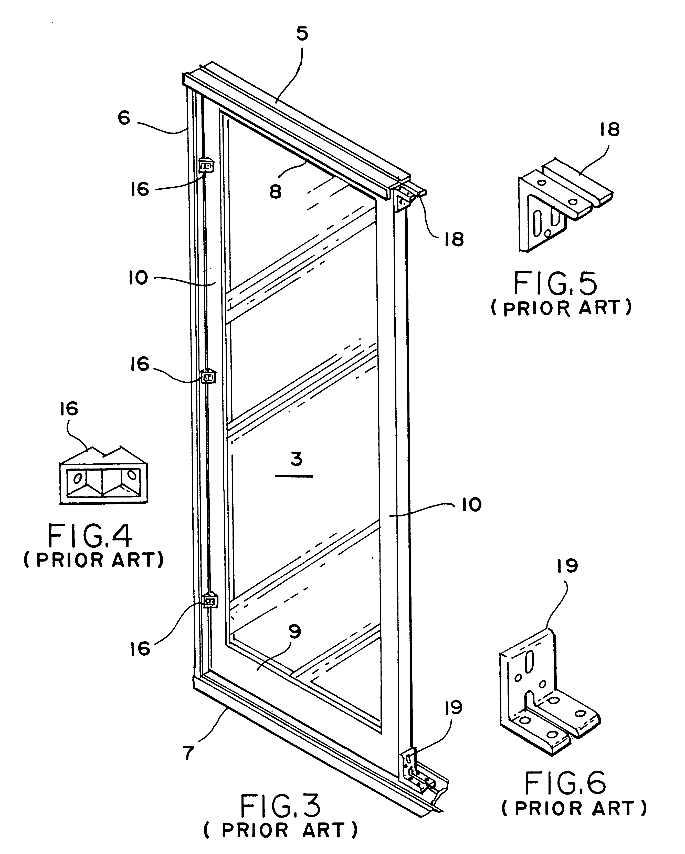
FIG. 3 is a partially broken view of the door shown in FIG. 1 showing how the fixed panel is secured in place by a clip which joins the jam of the frame and upper and lower fixed panel brackets which secure the panel and render it immovable;

FIG. 4 is a perspective view of the clip utilized between the fixed panel and the jam;

FIG. 5 is a perspective view of the fixed panel bracket used at the top;

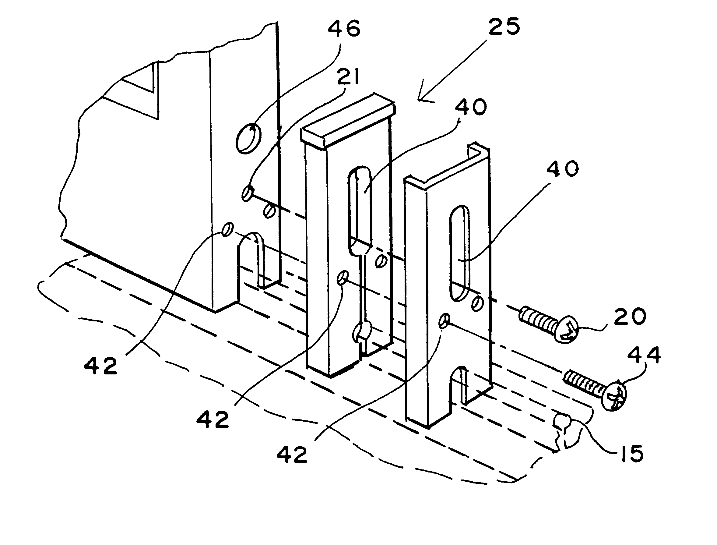
FIG. 6 is a perspective view of the fixed panel bracket used at the bottom;

FIGS. 7-10 show in sequence and diagramma...


PUM


Abstract

A moveable sliding glass door track clip guide, ideally formed of plastic, and attached to the bead on the top of the rail on the sill which is subsequently secured in place by a sliding glass door track clip cover which will inhibit the door from jumping the track in strong wind loads. The guide contributes significantly to the general security of the SGD installation, since SGD's, by design, must be lifted then set upon their track. The guide slidably engages the upper bead on the track on the sill and thus resists the effort of the door to jump off the track by actually gripping the track itself. The method of the present invention involves the steps of first positioning a moveable panel in place. Thereafter, the main attachment screw is removed, and passed through the clip assembly. Only after the track clip guide has been positioned over the bead on the rail. The track clip cover is then secured over the track clip guide to lock the lower jaws of the track clip guide against any scissor-like action which would assist in dislodging the same.

Description

The present invention relates primarily to sliding doors (hereinafter SGD), and more particularly to sliding glass doors in residential applications. More specifically, the present invention is directed to means for securing a sliding glass door to the track which will assist in primarily resisting wind loads against the door which would tend to bow the door and raise the same off the track.The field of the invention relates primarily to sliding glass doors(SGD) in which normally one or more panels are moveable and one or more panels are fixed. These are definitely old in the art. Most sliding glass door panels ride on a track or sill which has one or more rails, and the door panel has rollers on the lower portion which ride on the rails. While one or more of the panels may be sliding and one or more of the panels may be fixed, both panels are usually identical and equipped with rollers so that either can be a sliding panel. However, during installation, brackets are used in order t...

Claims


Application Information

Patent Timeline
IPC IPC(8): E05D15/06
CPCE05D15/066E05Y2201/614Y10S292/46Y10T16/37Y10T16/361Y10T16/3819E05Y2900/132
Inventor KRUSE, FREDERICK W.
Owner PGT INDS
Why Eureka
Try Eureka