Antenna device and radio equipment having the same

a radio equipment and antenna technology, applied in the direction of resonant antennas, substantially flat resonant elements, multiple-port networks, etc., can solve the problems of increasing cost and reducing antenna sensitivity

Inactive Publication Date: 2002-10-08
MURATA MFG CO LTD
View PDF8 Cites 214 Cited by
  • Summary
  • Abstract
  • Description
  • Claims
  • Application Information

AI Technical Summary

Benefits of technology

According to the present invention, the LC parallel resonance circuit is connected in series with the power supply side of the antenna conductor portion. Since the LC parallel resonance circuit resonates at a frequency nearly equal to the center frequency in the lower frequency band for transmitting and receiving a radio wave, an inductor component, caused by the LC parallel resonance circuit, is rendered to the antenna conductor portion, and thereby, the antenna conductor portion resonates at the center frequency in the lower frequency band to carry out the operation as an antenna.
In the arrangement of the present invention, no complicated circuits for changing the upper and lower frequency bands are provided as described above. Thus, the circuit configuration becomes simple, and the conduction loss can be reduced. Accordingly, the antenna sensitivity can be enhanced, and increase in cost can be prevented.

Problems solved by technology

Thus, problems arise in that the number of parts of the change-over circuit 43 is large, increasing the cost, the conduction loss in the change-over circuit 43 is large, reducing the antenna sensitivity, and so forth.

Method used


Image

  • Antenna device and radio equipment having the same
  • Antenna device and radio equipment having the same
  • Antenna device and radio equipment having the same

Examples


first embodiment

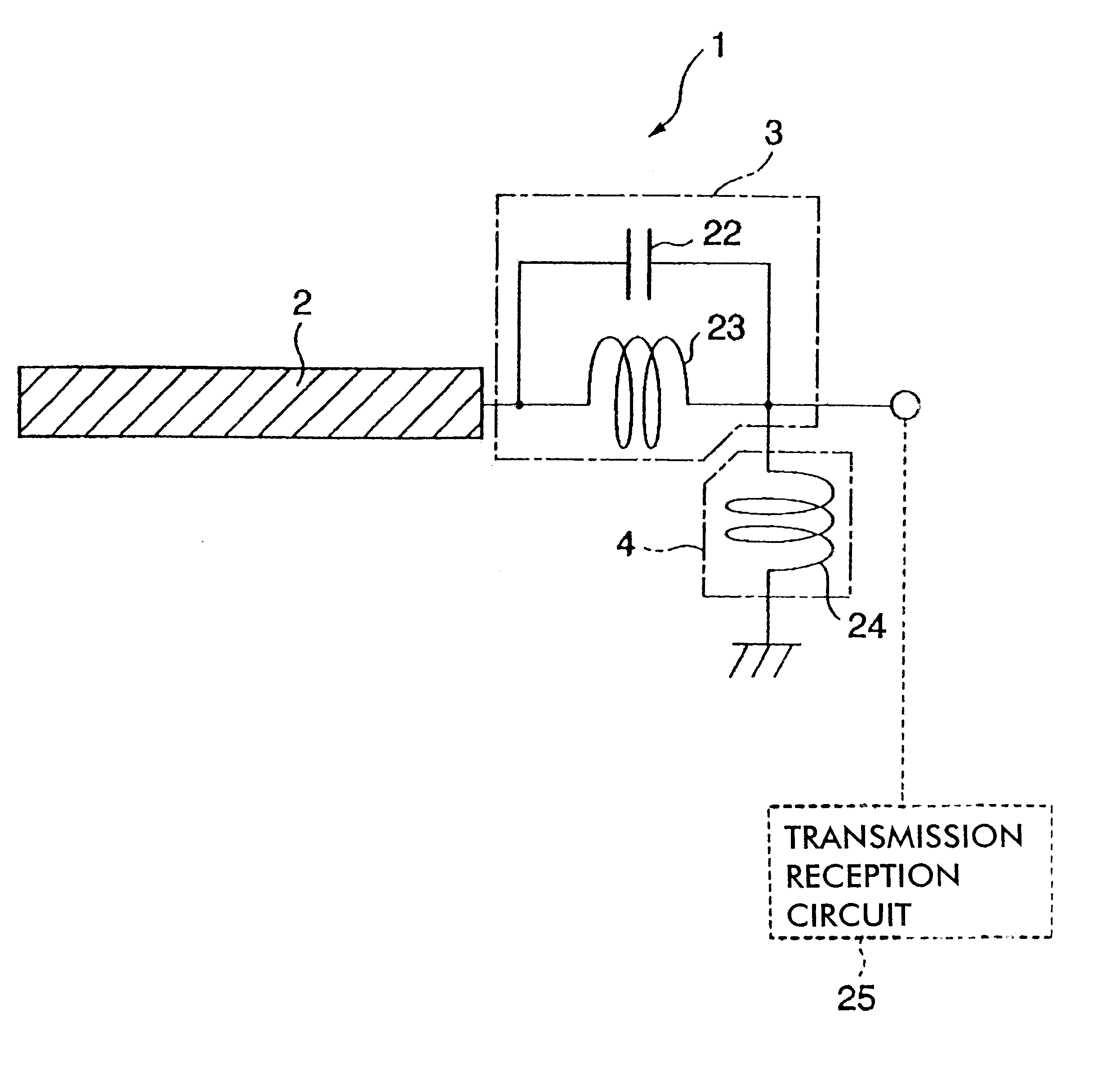
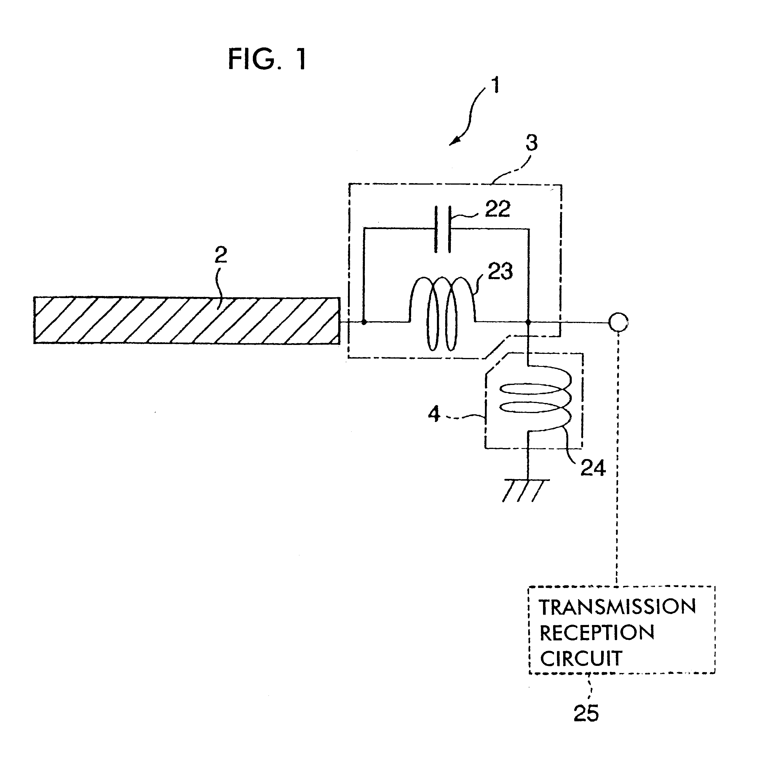
The antenna conductor portion 2 is made of a conductor material, and operates to transmit and receive radio waves. Different forms of the antenna conductor portion 2 are available. Any one of a plurality of the forms of the antenna conductor portion 2 may be employed in the FIGS. 4A to 7B show examples of the forms, respectively.

In the example of FIG. 4A, the antenna conductor portion 2 comprises a conductor film (conductor portion) 7 for transmission-reception of radio waves, which is formed on the surface of a substrate 6 made of a dielectric or magnetic material. In the example of FIG. 4B, the antenna conductor portion 2 is formed of a conductor wire which comprises a conductor wire member of a helical antenna portion 9 provided in the top of a whip antenna portion 8. In the example of FIG. 4B, the antenna conductor portion 2 comprises a combination of the whip antenna portion 8 with the helical antenna portion 9 connected to each other, as described above. The antenna conductor...

second embodiment

In the second embodiment, the inductor portion 23 constituting the LC parallel resonance circuit 3 comprises two inductors 26 and 27 connected in series with each other, as shown in FIG. 8. One end of a capacitor 28 is connected to the node A between the inductors 26 and 27. The other end of the capacitor 28 is connected to the anode side of a PIN diode 29. The cathode side 29 of the PIN diode 29 is connected to the power supply side of the inductor 27.

Moreover, one side of a resistor 30 is connected to the node B between the capacitor 28 and the PIN diode 29. A capacitor 31 is incorporated between the other side of the resistor 30 and ground. A voltage input portion 32 is electrically connected to the node C between the resistor 30 and the capacitor 31.

Referring to the properties of the PIN diode, the resistance to an AC signal varies correspondingly to DC current flowing through the PIN diode. When no DC current flows through the PIN diode, the resistance to an AC signal becomes v...

third embodiment

In the third embodiment, characteristically, the capacitor portion 22 contains a varicap diode. Regarding the varicap diode, the parasitic capacitance continuously varies correspondingly to applied voltage. Accordingly, the capacitance C of the capacitor portion 22 can be easily varied by changing the voltage applied to the varicap diode. Therefore, the resonance frequency of the LC parallel resonance circuit 3 is varied only by changing the voltage applied to the varicap diode. Thus, the lower frequency band for transmitting and receiving radio waves can be varied and set correspondingly to the specifications of the antenna device 1. Needless to say, the higher frequency band can be also varied and set.

For the capacitor portion 22 having the varicap diode, various circuit configurations can be provided. For example, the capacitor portion 22 comprises a single varicap diode 36 in the example of FIG. 13A. A resistor 37 and a capacitor 38 connected in series with each other are connec...


PUM


Abstract

An LC parallel resonance circuit is connected in series with the power supply side of the antenna conductor portion. The antenna conductor portion is configured so as to resonate at a frequency slightly lower than the center frequency in the higher frequency band of two frequency bands for transmitting and receiving radio waves. The LC parallel resonance circuit is configured so as to resonate substantially at the center frequency in the lower frequency band for transmitting and receiving a radio wave and be capable of providing to the antenna conductor portion a capacitance for causing the antenna conductor portion to resonate at the center frequency in the higher frequency band. Thus, a circuit for changing the upper and lower frequency bands is not needed. Such a change-over circuit, which is complicated, causes problems in that the conduction loss increases, and the antenna sensitivity deteriorates. Without need of the change-over circuit, the conduction loss can be reduced, the antenna sensitivity can be enhanced and costs can be reduced.

Description

1. Field of the InventionThe present invention relates to an antenna device which is contained in radio equipment such as a portable telephone, and so forth, and to radio equipment provided with the same.2. Related ArtFIG. 18 schematically shows an example of a dual band type antenna device. An antenna device 40 shown in FIG. 18 can transmit or receive radio waves in two different frequency bands, and comprises an antenna conductor portion 41, an inductor portion 42, a change-over circuit 43 for changing the inductance of the inductor portion 42, and an inductor 44 which functions as a matching circuit.The antenna conductor portion 41 has, for example, a form of a conductor wire member such as a whip antenna or the like, a conductor film formed on the surface of a rectangular parallelepiped substrate, and so forth. The inductor portion 42 is connected in series with the power supply side of the antenna conductor unit 41, and the inductance component of the inductor portion 42 is cou...

Claims


Application Information

Patent Timeline
Patent Type & Authority Patents(United States)
IPC IPC(8): H01Q1/24H01Q5/00H01Q9/04H01Q1/38H01Q1/50H01Q5/10H01Q5/335H01Q13/00H04B1/3822H04B1/40
CPCH01Q1/243H01Q5/335H01Q9/0407H01Q13/00
Inventor KUSHIHI, YUICHI
Owner MURATA MFG CO LTD
Why Eureka
Try Eureka