
Method and apparatus for processing visual information

a visual information and processing method technology, applied in the field of visual information processing methods and apparatuses, can solve the problems of inability to give human knowledge of environments that are not known to humans, inability to estimate the three-dimensional structure from only given information, and inability to give information about the environmen

Inactive Publication Date: 2002-10-15
CANON KK
View PDF12 Cites 7 Cited by
  • Summary
  • Abstract
  • Description
  • Claims
  • Application Information

AI Technical Summary

Problems solved by technology

If an image is considered to a portion of visual information, the essential issue in processing visual information is an assumption of three-dimensional visual information from the obtained two-dimensional image.
A problem estimating the three-dimensional structure from only given information is ill-posed because the solution is intermediate.
Systems, treatment of movable objects is too complex.
1. A method of recognizing a minimum unit of an object constituting knowledge has not been discussed. That is, the discussion has been performed on the assumption that the recognition of the minimum unit is easy.
2. The description has been performed that the knowledge is described by a knowledge engineer. That is, knowledge of environments that is not known by human beings cannot be given.
However, since input / output data and the structures of the neural network are general structures, hierarchical structure cannot always be acquired.
Moreover, even if the neural network has the performance for acquiring the hierarchical structure, it can be expected that an excessively long time is required.
However, the foregoing encoding contains considerable redundancy in a sense that an intense correlation exists between local patterns which are spatially adjacent.

Method used


Image

  • Method and apparatus for processing visual information
  • Method and apparatus for processing visual information
  • Method and apparatus for processing visual information

Examples


second embodiment

A second embodiment has a structure such that the stochastic automaton 7 according to the first embodiment is realized by a Hopfield-type network. As a result, the process to be performed in an input parameter controller 208 is changed.

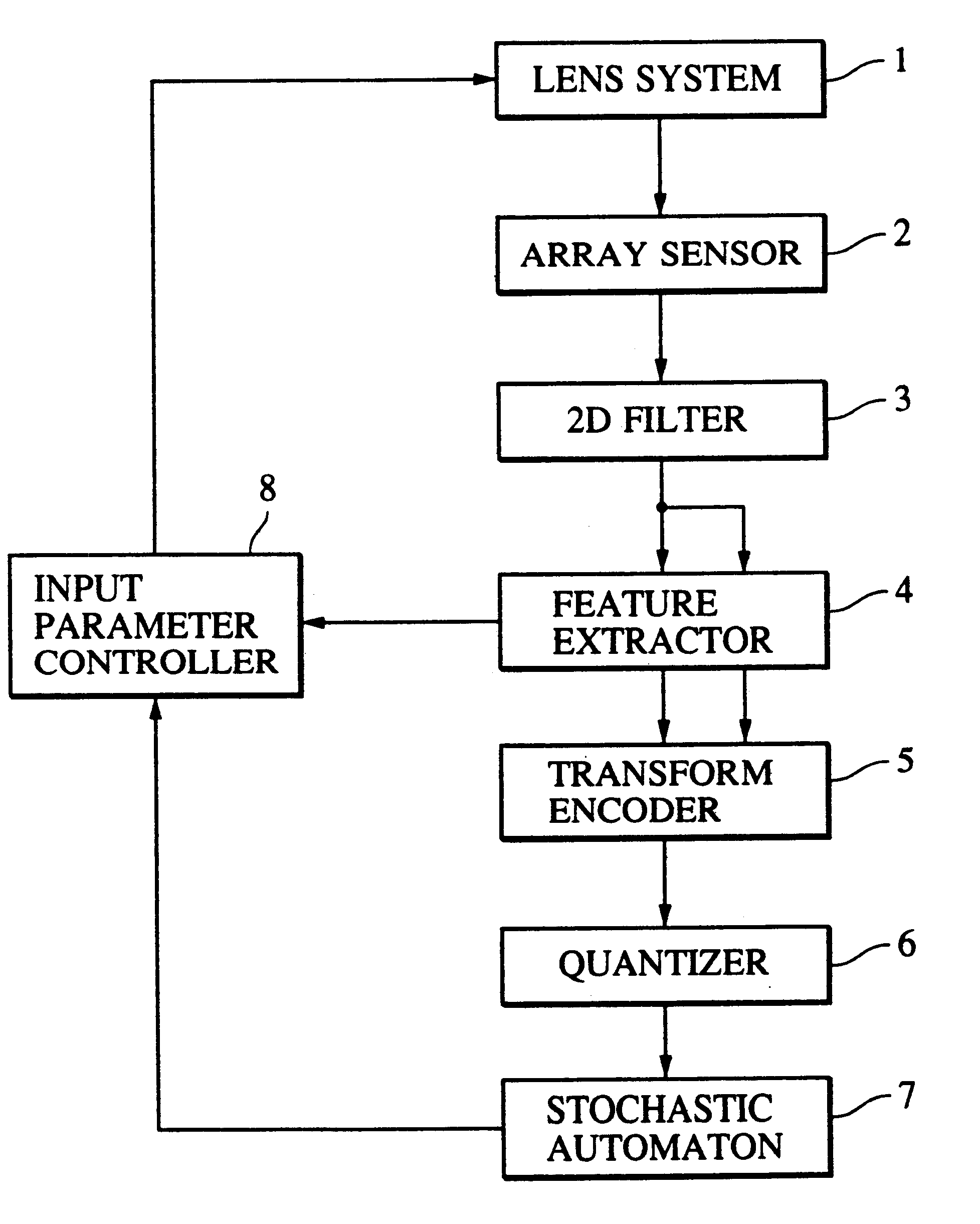
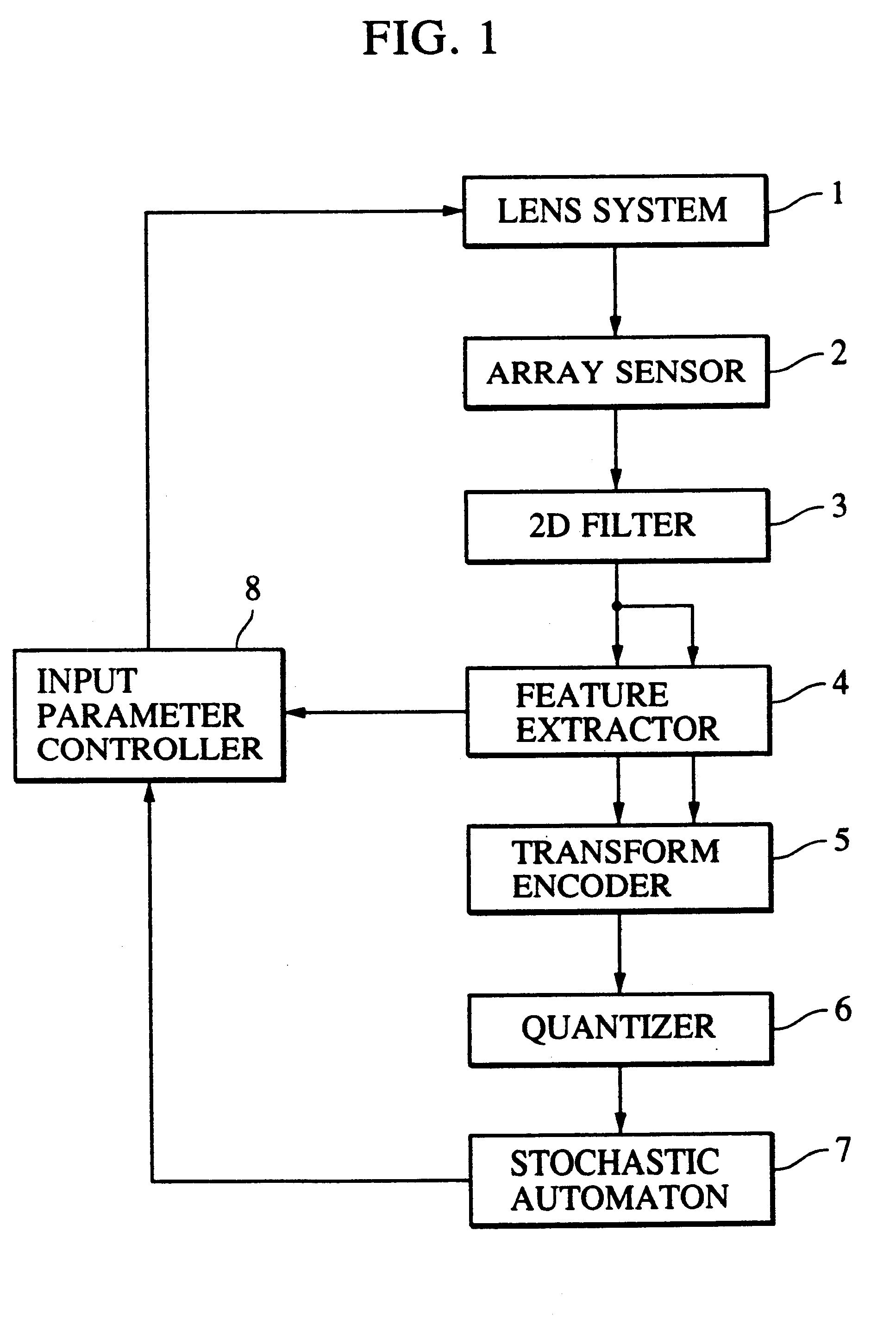
FIG. 10 is a block diagram showing an example of the structure of a visual-information processing apparatus according to this embodiment. A lens system 201, an array sensor 202, a 2D filter 203, a feature extractor 204 and a transform encoder 205 respectively are same as the lens system 1, the array sensor 2, the 2D filter 3, the feature extractor 4 and the transform encoder 5 according to the first embodiment.

Quantizer 206

FIG. 11 shows the structure of a quantizer 206. The quantizer 206 has a learning mode for acquiring representative vectors and an execution mode for encoding the supplied signal. The representative vectors are acquired in the learning mode by a method using a correlation matrix or a method using a learning vector quantizer suggested...

third embodiment

A third embodiment has a structure in which the visual-information processing apparatus according to the present invention is applied to a monitoring apparatus.

FIG. 13 is a block diagram showing an example of the structure of a monitoring apparatus according to this embodiment. The lens system 301, the array sensor 302 and the 2D filter 303 are similar to the lens system 1, the array sensor 2 and the 2D filter 3 according to the first embodiment.

Feature Extractor 304

A feature extractor 304 detects the extreme value of time change of the image data as well as the feature about the spatial arrangement detected by the 2D filter 303. The monitoring apparatus is positioned in a place, such as a shop or an office, in which a moving object is not substantially exist in usual. If no accident takes place, image data is not changed. Therefore, a place, the image data of which has been changed, is required to be observed in detail. As a result, the time monitored information is able to record ...

fourth embodiment

In the fourth embodiment, the quantizer 6 according to the first embodiment is realized by a learning local vector quantizer and the stochastic automaton 7 is realized by a symmetry-connected-type neural network group. Moreover, there are provided a signal input portion for inputting a signal from outside and a signal output portion for transmitting a signal to the outside are provided. As a result, a process to be performed by the input parameter controller is changed.

FIG. 15 is a block diagram showing an example of the structure of a visual-information processing apparatus according to this embodiment. An image input unit 401 comprises a lens system and an array sensor similar to the lens system 1 and the array sensor 2 according to the first embodiment. A 2D filter 403, a feature extractor 404 and a transform encoder 405 are similar to the 2D filter 3, the feature extractor 4 and the transform encoder 5 according to the first embodiment.

Quantizer 406

FIG. 16 shows the structure of...


PUM


Abstract

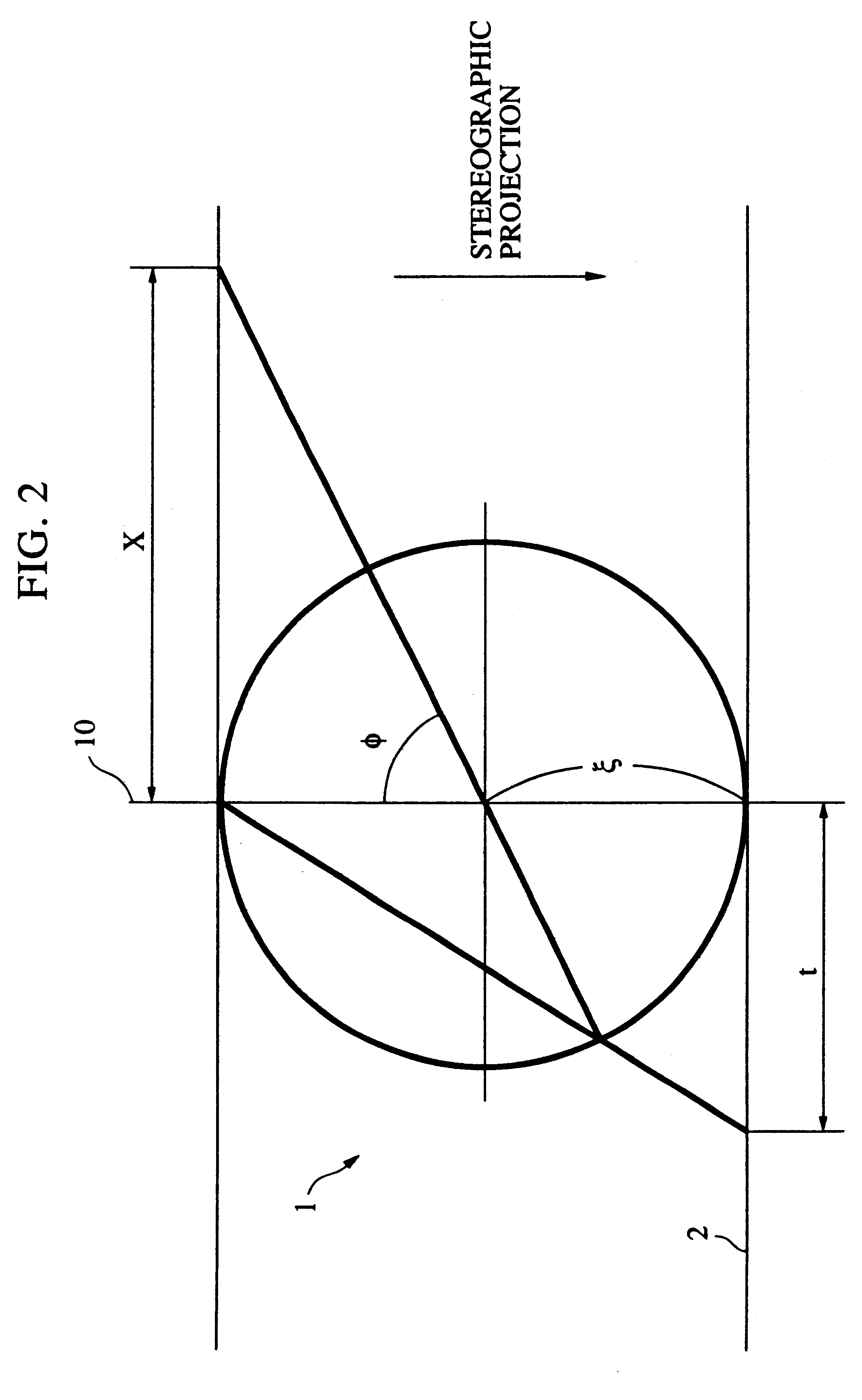
A 2D image supplied from an image input unit including a wide view lens is sampled into a discrete form by an array sensor, and then mapped to a multi-resolution space by a 2D filter. The feature of the supplied image is detected, and then the mapped image is transformed to a local pattern about the detected feature, and then the coordinates of the position of the feature and the code word of the local pattern are formed into a set which is then encoded. The code is supplied to each cell of a stochastic automaton. The quantity of visual information is calculated in accordance with the quantity of mutual information between different cells of the stochastic automaton consisting of cells in blocks, the coordinates of the position of the feature and the distance from the feature to the optical axis so as to control the optical axis of the image input unit in such a manner that the quantity of visual information is maximized.

Description

1. Field of the InventionThe present invention relates to a method and apparatus for processing visual information which are capable of appropriately processing visual information and which can be adapted to, for example, an input unit, an image encoding and decoding unit, an image recognition unit, an image restoring unit, a monitoring unit, an autonimic vehicle or an autonomic robot.2. Related Background ArtLiving organisms have a function capable of accurately recognizing the surrounding environment to the extent of a necessity by using a finite number of processing units and dealing with the recognized environment. The dynamic range of each signal required to recognize the environment is very wide if all possible situations are assumed. As for visual information for example, visual sensors of a living organism are, as a matter of course, finite. However, the environment extends in all azimuths. Therefore, a living organism having no transferring means must input signals with req...

Claims


Application Information

Patent Timeline
Patent Type & Authority Patents(United States)
IPC IPC(8): G06T5/20
CPCG06T5/20
Inventor WASHIZAWA, TERUYOSHI
Owner CANON KK
Learn More