Speaker mounting device

a mounting device and speaker technology, applied in the direction of light support devices, washstands, scaffold accessories, etc., can solve the problems of difficulty and inconvenience in dismounting and remounting the speaker enclosure for maintenance or replacement, and the wall sheathing is typically unsuitable for supporting substantial loads

Inactive Publication Date: 2002-11-26
MS ELECTRONICS
View PDF6 Cites 30 Cited by
  • Summary
  • Abstract
  • Description
  • Claims
  • Application Information

AI Technical Summary

Problems solved by technology

Unfortunately, a number of problems are encountered when attempting to do so, including difficulty locating studs or similar structures capable of supporting the speaker enclosure and a mounting mechanism, and difficulty and inconvenience in dismounting and remounting the speaker enclosure for maintenance or replacement.
The wall sheathing is typically unsuitable for supporting substantial loads, such as the speaker enclosure, so any such load mounted on the surface must be secured to one or more underlying studs for reliable support.
Unfortunately, it will be appreciated, locating the studs hidden beneath the sheathing can be very difficult.
Furthermore, fasteners driven into the an improperly located stud may split or otherwise damage the stud and fail to provide the desired support.
Additionally, recent developments in home theater systems have resulted in speaker enclosures that are larger and heavier than those previously used, thereby making the mounting thereof even more difficult.
Unfortunately, many existing mounting schemes do not allow for convenient dismounting and remounting, and some require that the mounting mechanism itself be dismounted and remounted or that the fasteners be withdrawn and reapplied to the studs.
It will be appreciated that either action can result in damage to the sheathing or the studs and may ultimately undermine their supportive qualities and cause structural failure.

Method used


Image

  • Speaker mounting device
  • Speaker mounting device
  • Speaker mounting device

Examples


first embodiment

FIG. 3 is a front perspective view of a preferred first embodiment of a corner bracket portion of the present invention;

second embodiment

FIG. 4 is a font perspective view of a preferred second embodiment of the corner bracket portion of the present invention;

FIG. 5 is an exploded isometric view of a preferred first embodiment of a mounting plate portion of the present invention;

FIG. 6 is an exploded top plan view of the mounting plate portion shown in FIG. 5;

FIG. 7 is an exploded top plan view of a preferred second embodiment of the mounting plate portion of the present invention; and

third embodiment

FIG. 8 is a top plan view of a preferred third embodiment of the mounting plate portion of the present invention.

DETAILED DESCRIPTION OF A PREFERRED EMBODIMENT

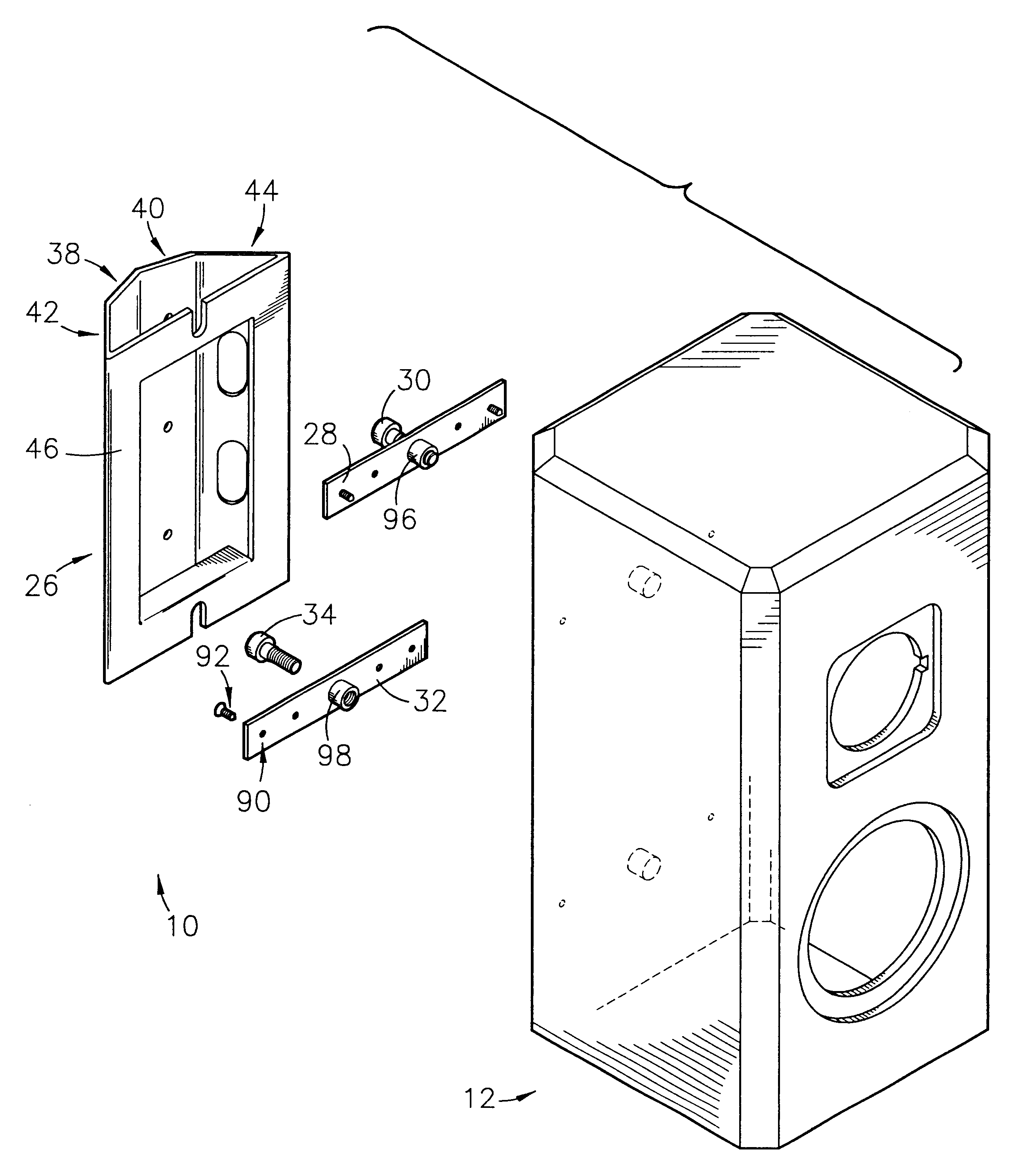
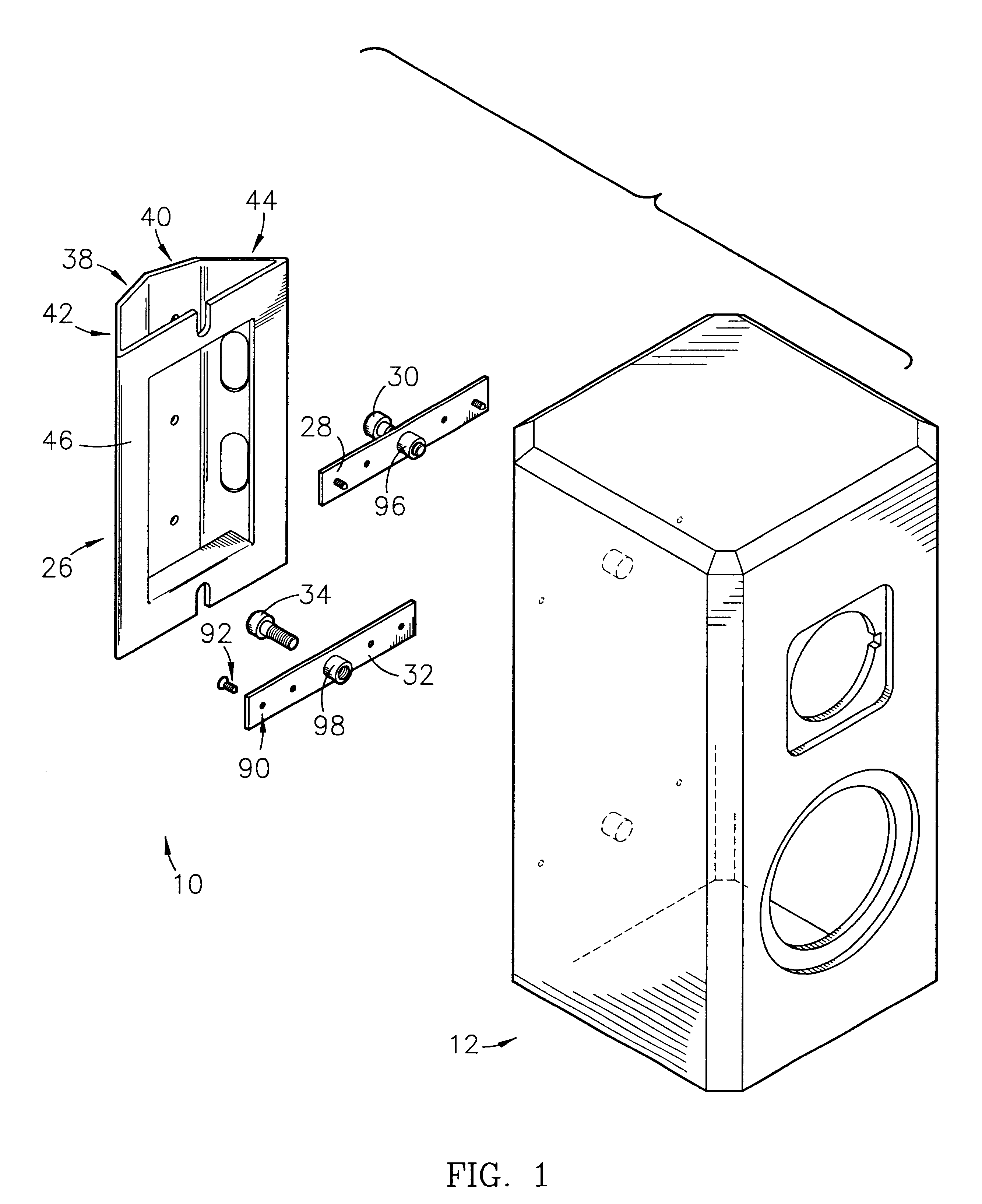
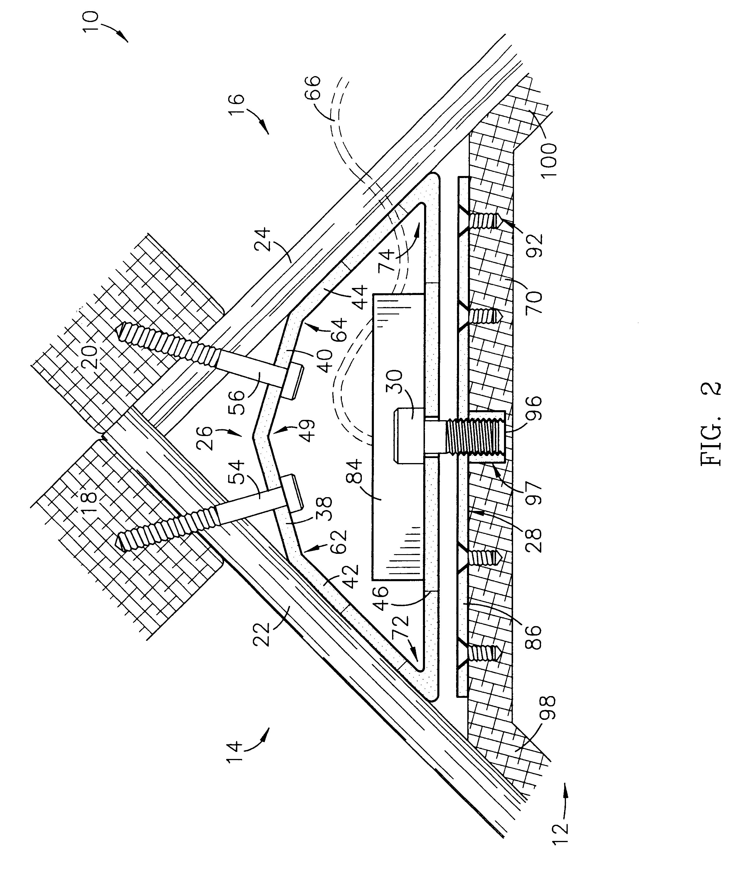
Referring to FIGS. 1, 2, and 3, a speaker mounting device 10 is shown constructed in accordance with a preferred embodiment of the present invention, and operable to mount a speaker enclosure 12 in an elevated position at an intersection of two walls 14,16, a wall and a ceiling, or similar structures, wherein the device 10 facilitates easily locating supportive wall studs 18,20 underlying wall sheathings 22,24, and the device 10 is adapted to couple with and support the speaker enclosure 12 in such a manner as to allow for dismounting and remounting the speaker enclosure 12 from and on the device 10 without dismounting the device itself from the walls 14,16. The preferred speaker mounting device 10 broadly comprises a corner bracket 26; an upper mounting plate 28, including an upper fastener 30; and a lower mounting plate 32, ...


PUM


Abstract

A mounting device (10) for mounting a speaker enclosure (12) in an elevated position at an intersection of two walls (14,16) or similar surfaces, wherein the device (10) facilitates easily locating supportive wall studs (18,20) underlying wall sheathings 22,24, and the device (10) is adapted to couple with and support the speaker enclosure (12) in such a manner as to allow for removing and replacing the speaker enclosure (12) from or on the device (10) without removing a corner bracket (26,226) component of the device (10) from the wall (14,16).

Description

1. Field of the InventionThe present invention relates to a mounting device for mounting a speaker enclosure or cabinet in an elevated position at a vertical or horizontal intersection of two walls, a wall and a ceiling, or similar structures, wherein the device facilitates easily locating supportive studs underlying surface sheathings, and is adapted to couple with and support the speaker enclosure in such a manner as to allow for dismounting and remounting the speaker enclosure from or on the device without dismounting the device itself from the structures.2. Description of the Prior ArtThose with skill in the art of home audio or theater systems and speaker enclosures or cabinets will appreciate that it is often desirable to mount a speaker enclosure in an elevated position at a vertical or horizontal intersection of two walls, a wall and a ceiling, or similar structures. Unfortunately, a number of problems are encountered when attempting to do so, including difficulty locating s...

Claims


Application Information

Patent Timeline
Patent Type & Authority Patents(United States)
IPC IPC(8): A47B81/00H04R1/02
CPCA47B81/002H04R1/026
Inventor COMBEST, CHRISTOPHER E.
Owner MS ELECTRONICS
Why Eureka
Try Eureka