Screw capper

a screw and capper technology, applied in the direction of screw stopper insertion, cap, rotating screw, etc., can solve the problems of scarring or crash of the latter, easy abradability of rubber and/or soft resin, and risk of allowing the vessel to rota

Inactive Publication Date: 2003-02-18
SHIBUYA IND CO LTD
View PDF7 Cites 41 Cited by
  • Summary
  • Abstract
  • Description
  • Claims
  • Application Information

AI Technical Summary

Problems solved by technology

However, rubber and / or soft resin are readily abradable and the abrasion of these members has the risk of allowing the vessel to rotate, requiring a frequent replacement of the anti-rotation member.
Depending on the configuration of the vessel, the latter may be scarred or crashed.

Method used


Image

  • Screw capper
  • Screw capper
  • Screw capper

Examples


Embodiment Construction

An embodiment of the invention will now be described with reference to the drawings.

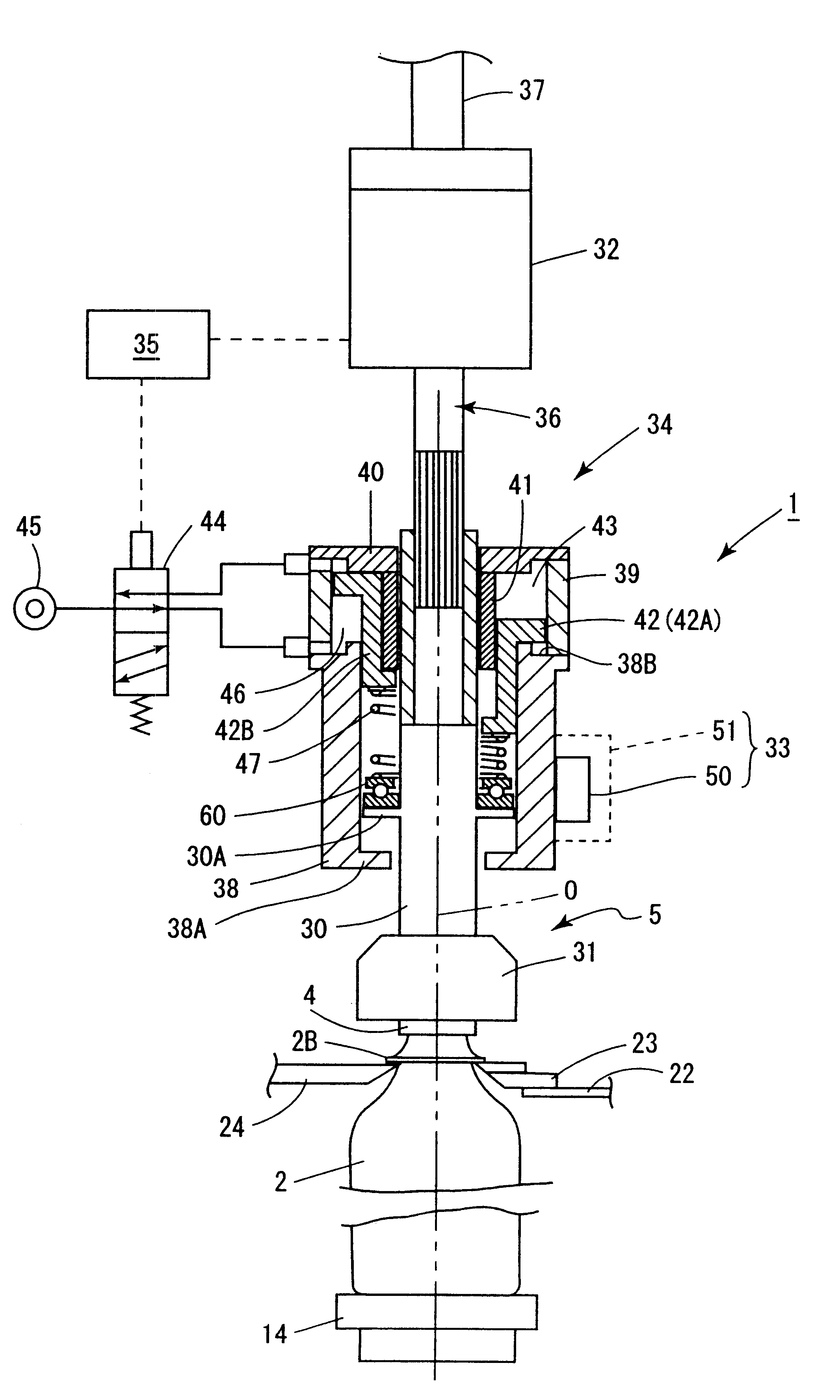
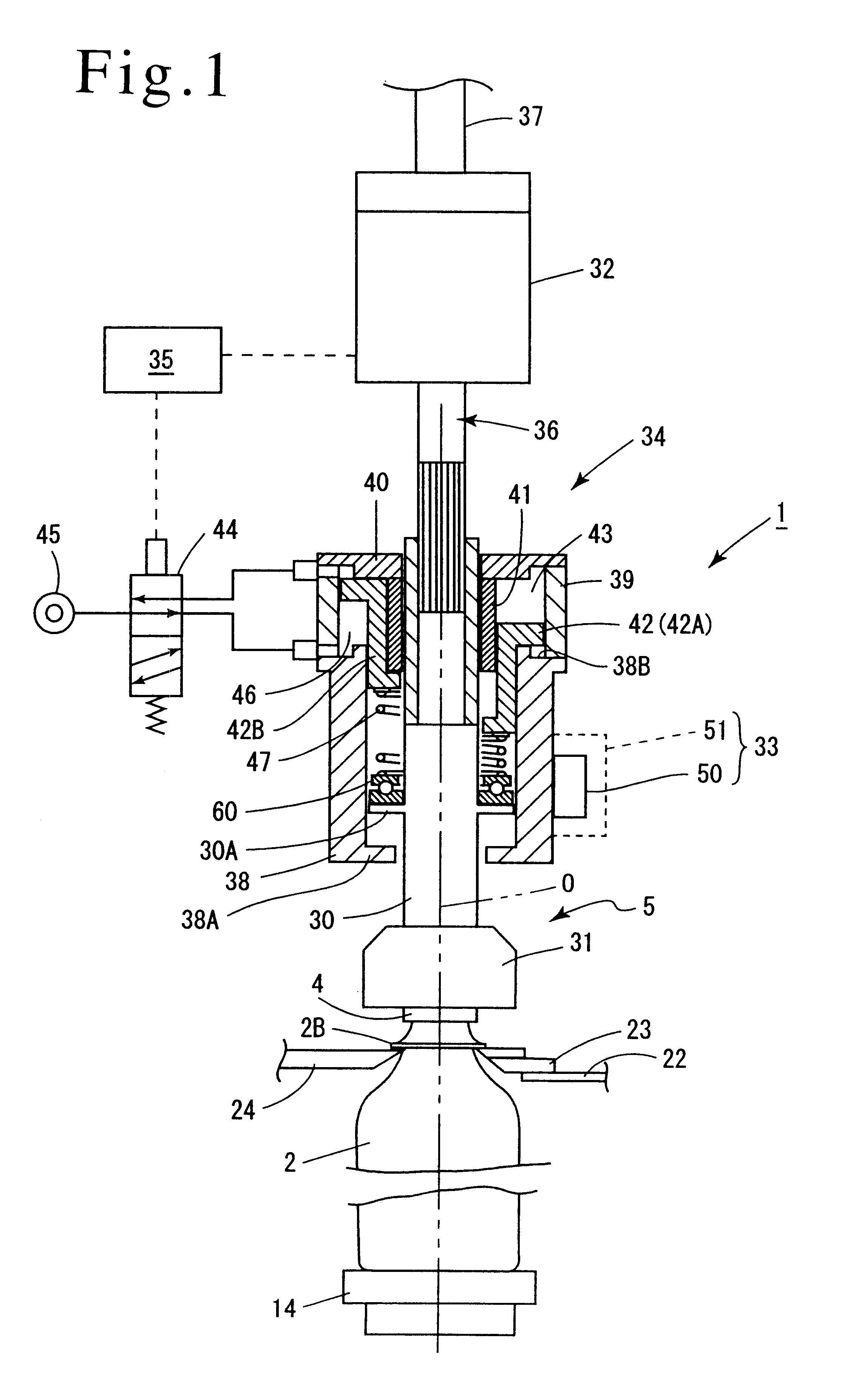
A rotary screw capper 1 is shown in FIGS. 1, 2 and 3, and comprises a revolving body 3 serving as conveying means which conveys a vessel 2, and a plurality of capping heads 5, each of which functions to screw and tighten a cap 4 onto the mouth 2A of the vessel 2.

The revolving body 3 is arranged to be driven by a drive source, not shown, to rotate clockwise, as viewed in FIG. 3, and a supply starwheel 10 which is disposed at a location adjacent to the revolving body feeds a vessel thereto, and the vessel 2 is discharged from the revolving body by a discharge starwheel 11.

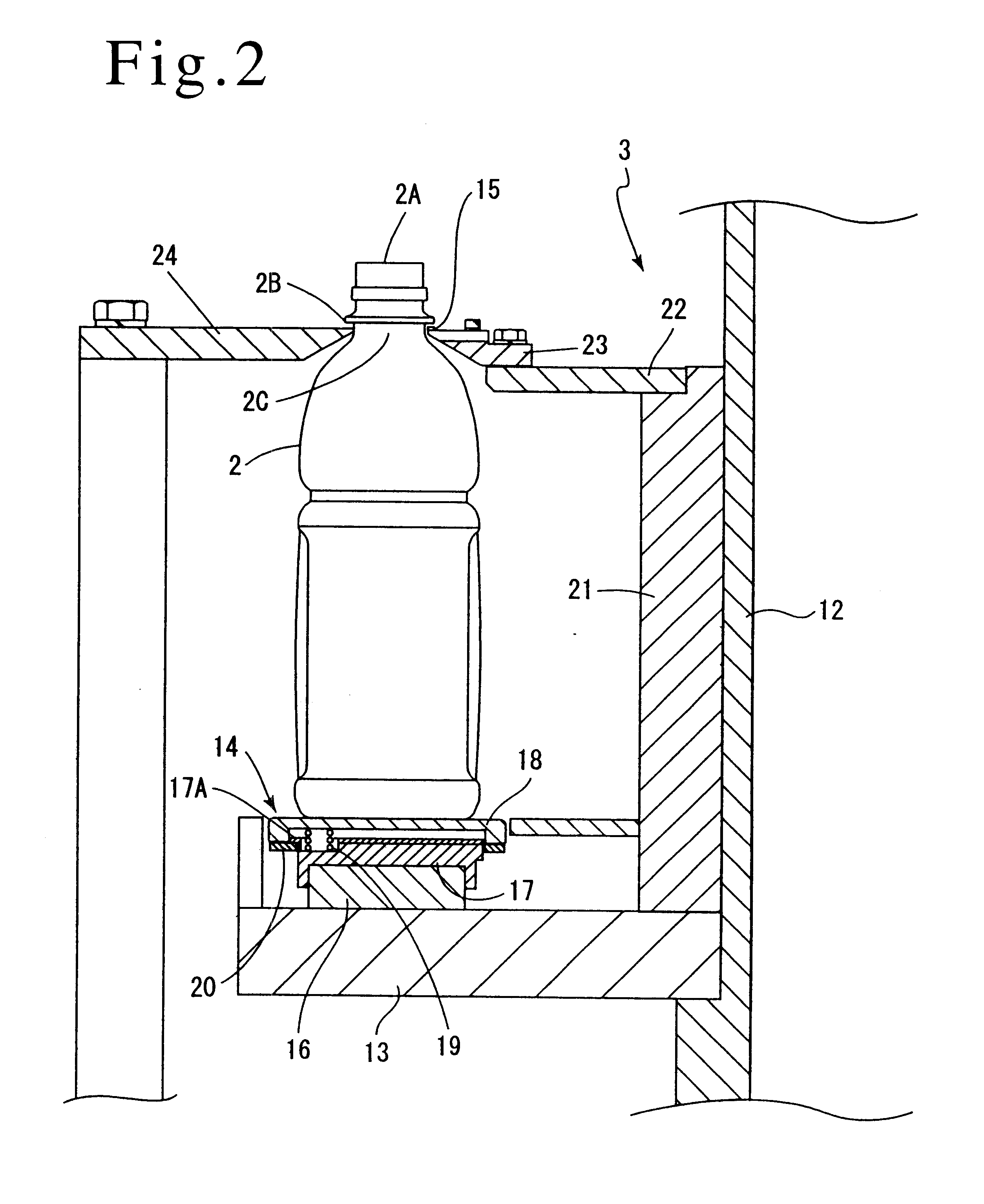
As shown in FIG. 2, the revolving body 3 comprises an upper disc 22 and a lower disc 13 which are mounted on the top and the bottom of a cylindrical member 21 which is integrally connected to a rotating stanchion 12 in the form of a cylinder. At an equal interval around the circumference, the upper disc 22 is formed with arcuate notch...


PUM


Abstract

A screw capper includes a capping head which comprises a chuck for holding a cap, a motor for driving the chuck for rotation, a cam mechanism for elevating the chuck, and an air cylinder for imparting a load to the chuck. A load imparted by the air cylinder is controlled by a controller to be zero from the beginning of a screwing and tightening operation until an angle of rotation of the chuck exceeds a specific angle where the load is changed, and is controlled to a higher value upon detection of an angle of rotation of the chuck which exceeds the specific angle in the course of the screwing and tightening operation. The arrangement allows a reliable screwing and tightening to be achieved as compared with the prior art while preventing a damage to threads or the occurrence of a cocked cap.

Description

The invention relates to a screw capper which screws and tightens a cap on a vessel, and in particular, to a screw capper which screws and tightens a cap on a vessel formed of plastics.DESCRIPTION OF THE PRIOR ARTIn a screw capper directed to a vessel formed of plastics such as PET bottle or the like, a difficulty in constraining a readily deformable vessel with a gripper has been recognized, and in order to accommodate for this, a cap is screwed and tightened while applying a load on the vessel through the cap. An engaging pawl is caused to bite into the lower surface of a flange provided on the vessel in order to prevent the vessel from rotating during the screwing and tightening operation.Specifically, the cap is strongly urged against the vessel when a thread formed on the cap is urged against a thread formed on the vessel. If the relative positions of the beginning turns of the threads on the cap and the vessel were as shown in FIG. 4 such that a thread 4N on the cap and a thre...

Claims


Application Information

Patent Timeline
Patent Type & Authority Patents(United States)
IPC IPC(8): B65B7/28B67B3/20B67B3/00
CPCB65B7/2835B67B3/2033B67B3/2093B67B3/208B67B3/206
Inventor HIGASHIZAKI, TAKASHINAKAMURA, RYOHEIKITAMOTO, HIROAKIMIYAZAKI, TAKASHIISHII, MASARU
Owner SHIBUYA IND CO LTD
Why Eureka
Try Eureka