Chain

a technology of chain and pivoting action, applied in the field of chains, can solve the problems of its pivoting action being limited to a single plane and being impossible to place them in other desired relative positions

Inactive Publication Date: 2003-03-04
ORIENTAL CHAIN MFG
View PDF9 Cites 19 Cited by
  • Summary
  • Abstract
  • Description
  • Claims
  • Application Information

AI Technical Summary

Problems solved by technology

Although, while such a conventional roller chain is pivotable, its pivoting action is limited to a single plane.
Therefore, it has been required that the driving sprocket and the driven sprocket be placed in the same plane, and it has been impossible to place them in other desired relative positions.

Method used


Image

  • Chain
  • Chain
  • Chain

Examples


Embodiment Construction

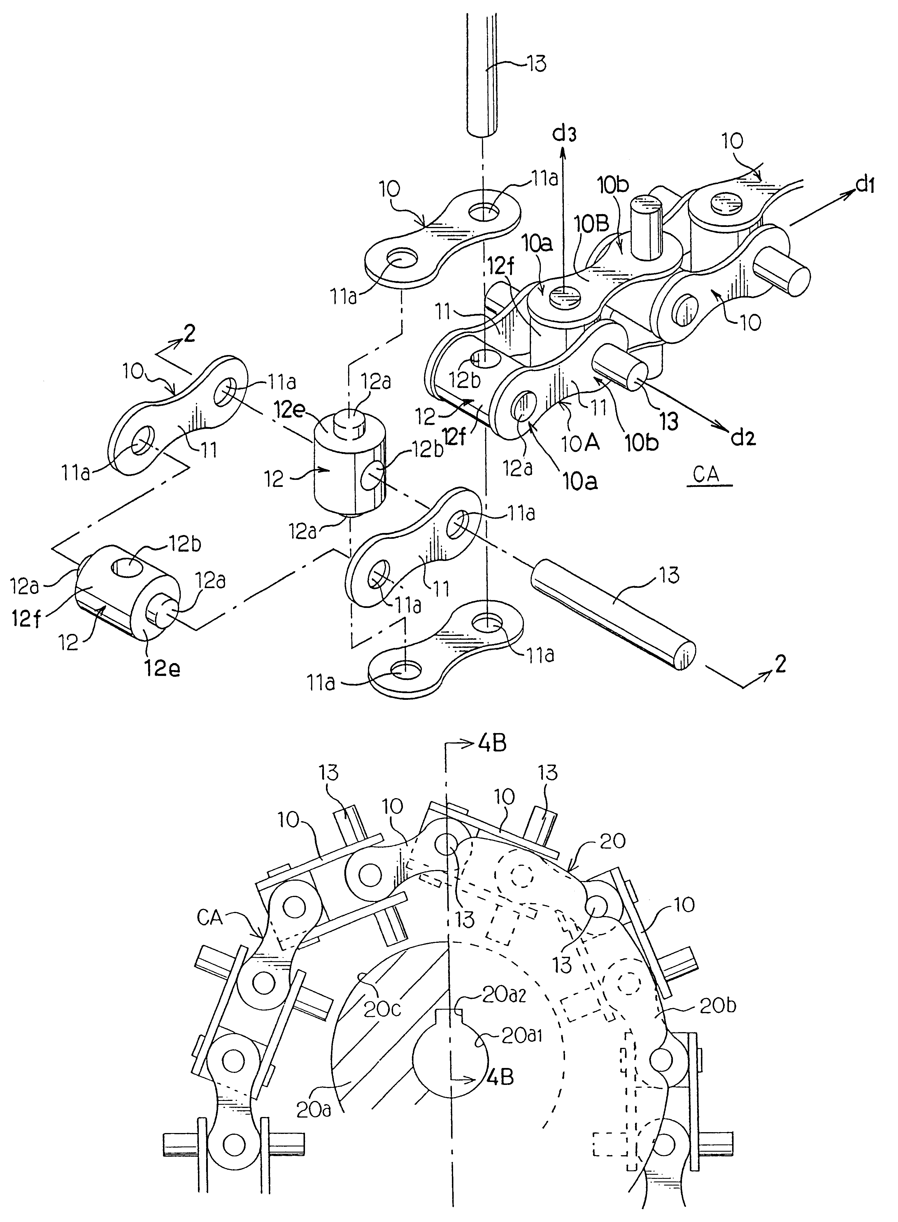
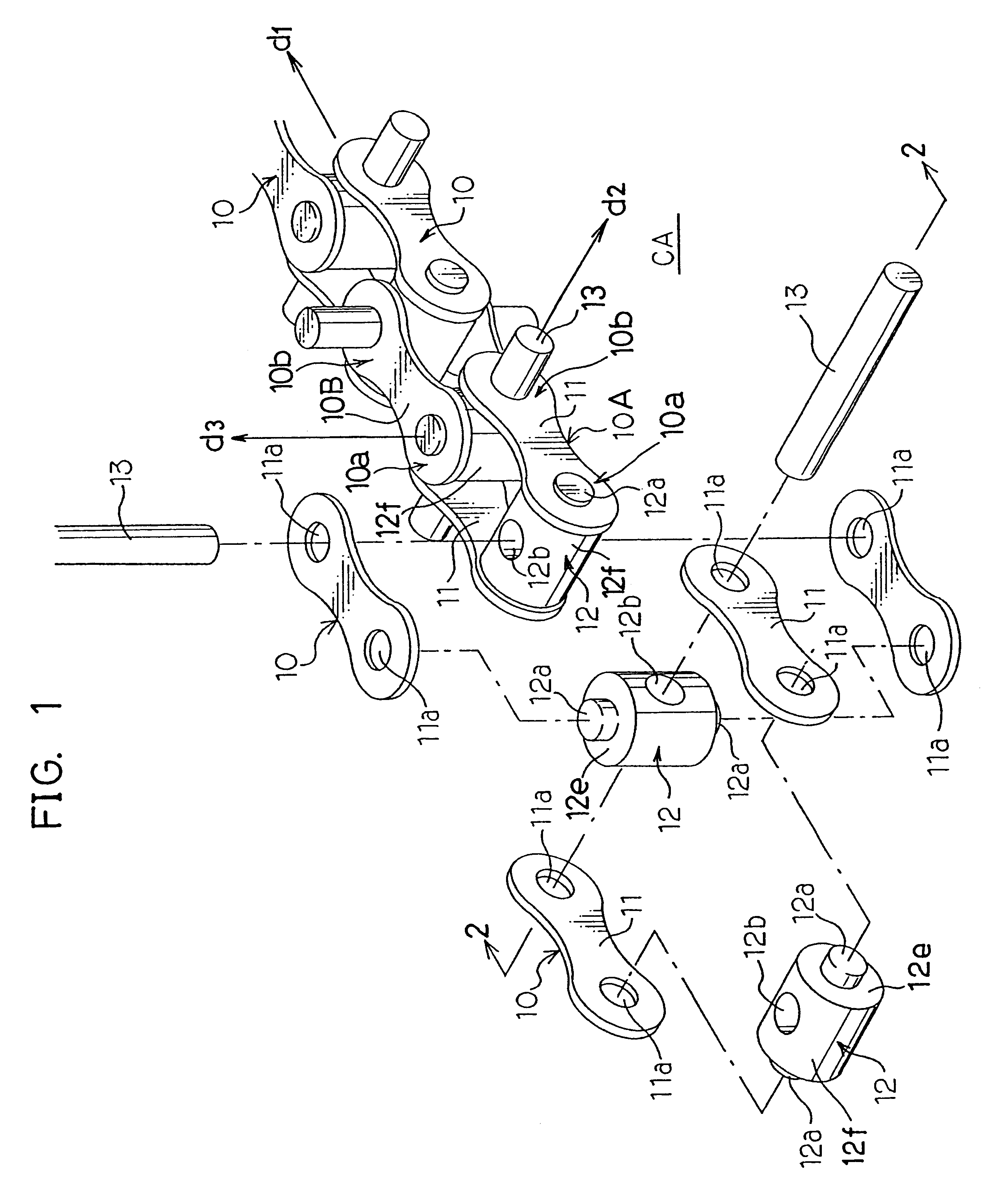
In one variation of the foregoing embodiment, engagement rollers 14 are mounted on both terminal portions of each connecting pin 13 which protrude outward through link plates 11 on both sides of each link unit 10 of a chain CA, as shown in FIGS. 5 and 6. A stopper ring 14a is mounted on both terminal portions of the connecting pin 13, outside the engagement rollers 14, and the extreme ends of the connecting pin 13 are flattened by pressing or hammering from outside to prevent the engagement rollers 14 from coming off the connecting pin 13. The engagement rollers 14 are rotatably mounted on the individual connecting pins 13 in this fashion. The chain CA of this variation of the embodiment can be wrapped on the sprocket 20 shown in FIG. 3 so that the engagement rollers 14 rest in the engagement recesses 20b1 in the sprocket 20.

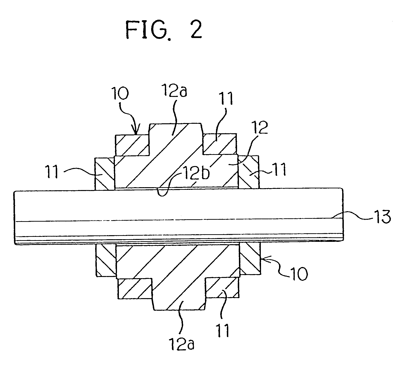
In another variation of the embodiment, a pin-fitting hole 12b formed in each connecting stud 12 has a generally elliptical cross section elongated in the direc...


PUM

PropertyMeasurementUnit
anglesaaaaaaaaaa
degrees of freedomaaaaaaaaaa
cylindrical shapeaaaaaaaaaa

Abstract

A chain (CA) comprises a plurality of link units (10), each including a pair of link plates (11) and a connection member (12) placed between the link plates (11) at one end of each link unit (10). The link plates (11) of one link unit (10) are connected end to end with the link plates (11) of another link unit (10) by a connecting pin (13) in such a way that the link units (10) are angularly displaced by 90 degrees from one link unit (10) to another as viewed along an extending direction of the chain (CA), whereby the successive link units (10) of the chain (CA) can be alternately bent in two different directions. The chain (CA) thus constructed can be bent and run in desired directions.

Description

1. Field of the InventionThis invention relates to a chain whose successive link units have two degrees of freedom so that the chain can be pivoted and run in desired directions.2. Discussion of the Related ArtA roller chain is often used for transmitting a rotational driving force. The roller chain includes inner and outer link plates which are joined one after another by connecting pins. When mounted on a driving sprocket and a driven sprocket which are placed in a common plane, the roller chain can transmit a rotational driving force from the driving sprocket to the driven sprocket.Although, while such a conventional roller chain is pivotable, its pivoting action is limited to a single plane. Therefore, it has been required that the driving sprocket and the driven sprocket be placed in the same plane, and it has been impossible to place them in other desired relative positions.The invention provides a solution to the aforementioned problem with the conventional chain. Specificall...

Claims


Application Information

Patent Timeline
Patent Type & Authority Patents(United States)
IPC IPC(8): F16H7/00F16G13/00F16H7/06F16G13/02F16G13/10F16H7/14
CPCF16G13/02F16H7/06F16G13/10
Inventor TANEMOTO, ATSUHIROSAWAMORI, TADASU
Owner ORIENTAL CHAIN MFG
Why Eureka
Try Eureka