Locking hinge
a hinge and hinge plate technology, applied in the field of locking hinges, can solve the problem that the shoulder rests are not readily adaptable to paintball guns, and achieve the effect of reducing the number of hinges
- Summary
- Abstract
- Description
- Claims
- Application Information
AI Technical Summary
Problems solved by technology
Method used
Image
Examples
Embodiment Construction
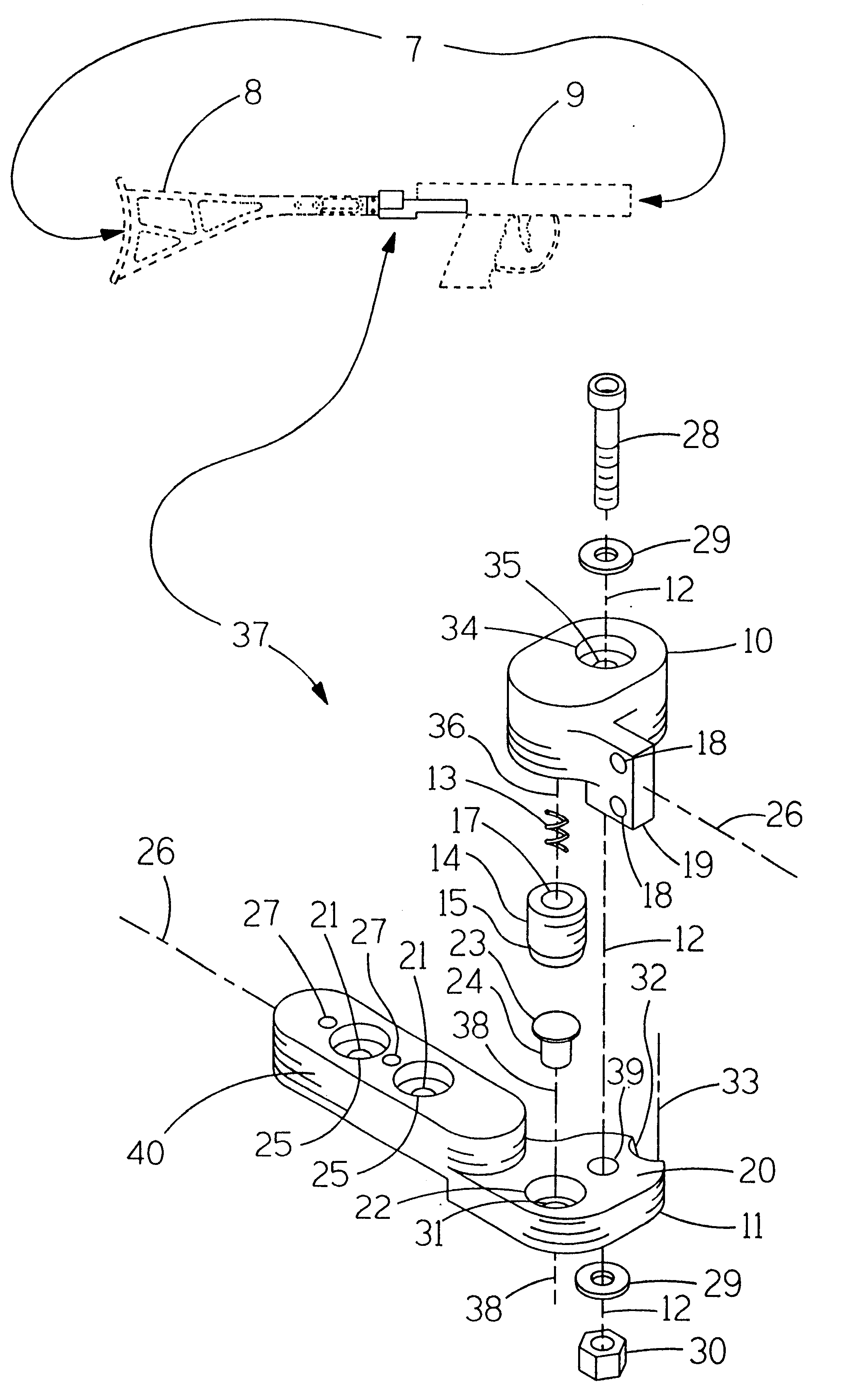
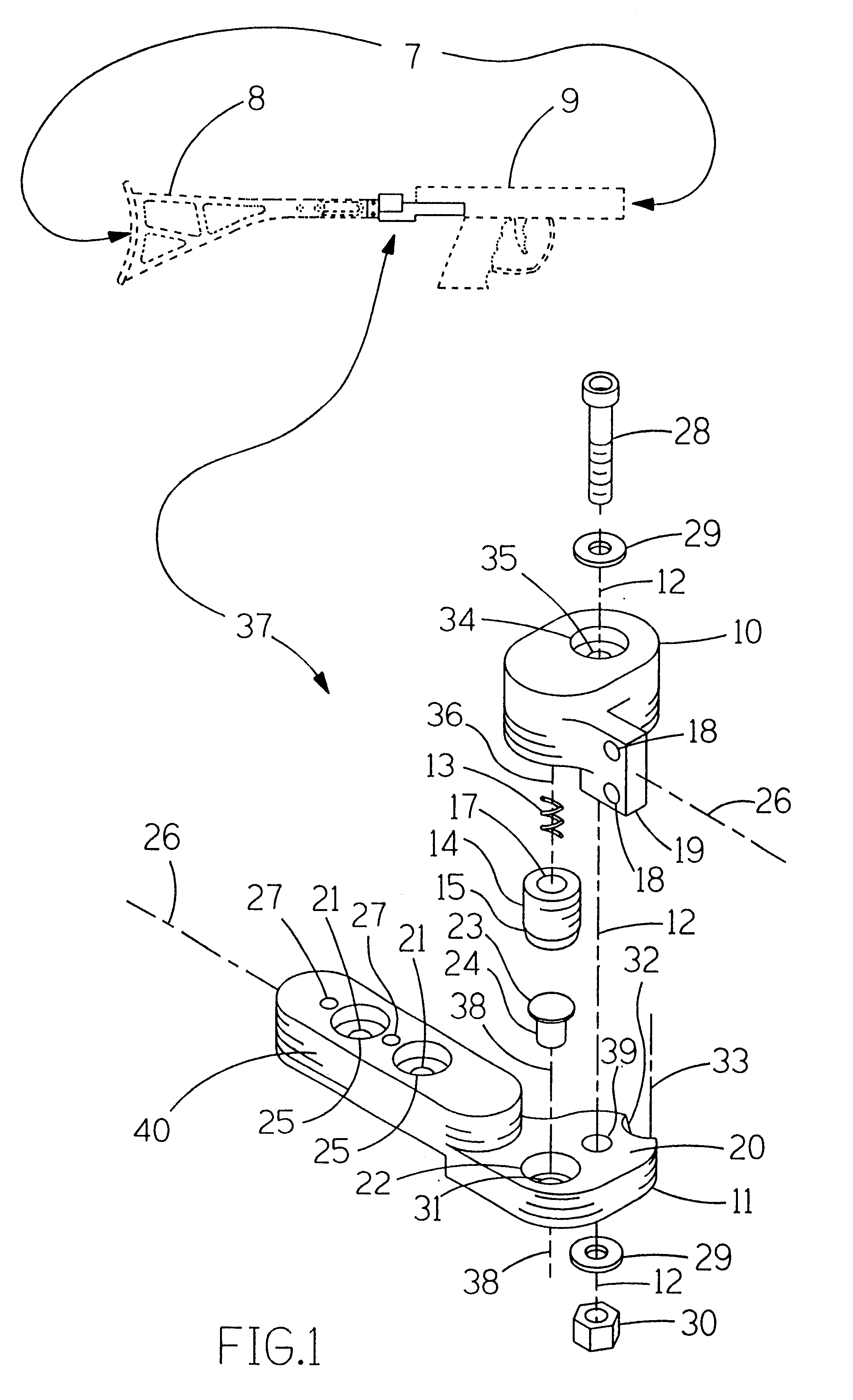
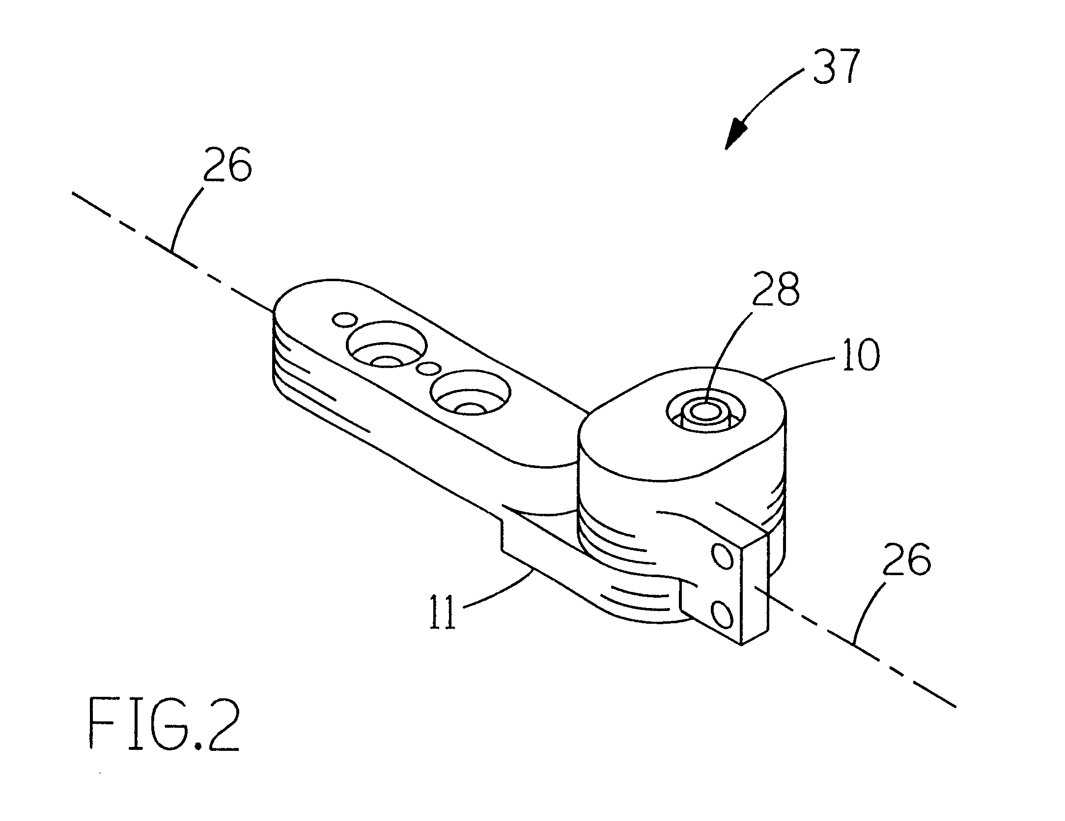
Referring now to the drawings, and more particularly FIGS. 1-3, there is shown a locking hinge 37. Generally, a locking hinge 37 includes a hinge joint axis 12, a first hinge plate 10, a second hinge plate 11, a spring 13, a locking cylinder 14 and a push button 24.
The locking hinge 37 is located between shoulder rest 8 and action 9 of paintball gun 7. Shoulder rest 8 is mounted to mounting arm 19 using mounting holes 18. Action 9 is mounted to mounting arm 40 using mounting holes 21.
Shown in FIGS. 4, 5 and 6, a first hinge plate 10 has a receiving counter bore 16 which contains a spring 13 and guides locking cylinder 14. One end of spring 13 contacts the bottom of counter bore 16. The other end of spring 13 contacts locking cylinder 14 through spring guide hole 17. Counter bore 16 allows locking cylinder 14 free movement along the axis of the locking mechanism 36. First hinge plate 10 has a symmetry axis 26. First hinge mounting holes 18 are equally spaced about the symmetry axis 2...
PUM
 Abstract
Description
Claims
Application Information
 - R&D
- Intellectual Property
- Life Sciences
- Materials
- Tech Scout
- Unparalleled Data Quality
- Higher Quality Content
- 60% Fewer Hallucinations
Browse by: Latest US Patents, China's latest patents, Technical Efficacy Thesaurus, Application Domain, Technology Topic, Popular Technical Reports.
© 2025 PatSnap. All rights reserved.Legal|Privacy policy|Modern Slavery Act Transparency Statement|Sitemap|About US| Contact US: help@patsnap.com


