Power amplifier configuration

a technology of power amplifiers and configurations, applied in the direction of amplifier modifications to reduce noise influence, amplifier modifications to reduce non-linear distortion, gain control, etc., can solve the problems of reducing the maximum obtainable efficiency of the system, and driving mechanical, thermal, and overhead powering costs. , to achieve the effect of improving the network, improving the reliability or flexibility, and improving the capacity

Inactive Publication Date: 2003-11-11
MICROSOFT TECH LICENSING LLC
View PDF6 Cites 135 Cited by
  • Summary
  • Abstract
  • Description
  • Claims
  • Application Information

AI Technical Summary

Benefits of technology

Another aspect provides a method of offering or providing a data transmission service over a network using such a power amplifier. As the advantages of the invention can enable a better network, which is more reliable or more flexible, or has greater capacity, or is more cost effective for example, consequently a data transmission service over the network can show a corresponding improvement, and the valu

Problems solved by technology

The high amplification levels required for such applications can lead to non-linear distortion of the data signal, which is undesirable.
A problem with known linear Power Amplifier (PA) technology is that a static back-off, proportional to the signal statistics (Complementary Cumulative Distribution Function (CCDF)), is required to obtain linearity in the system.
This back-off decreases the maximum obtainable efficiency of the system and drives mechanical, thermal, and overhead powering costs for wireless transmit architectures.
Known solutions include Envelope Elimination and Recovery (EER) but such solut

Method used


Image

  • Power amplifier configuration
  • Power amplifier configuration
  • Power amplifier configuration

Examples


Embodiment Construction

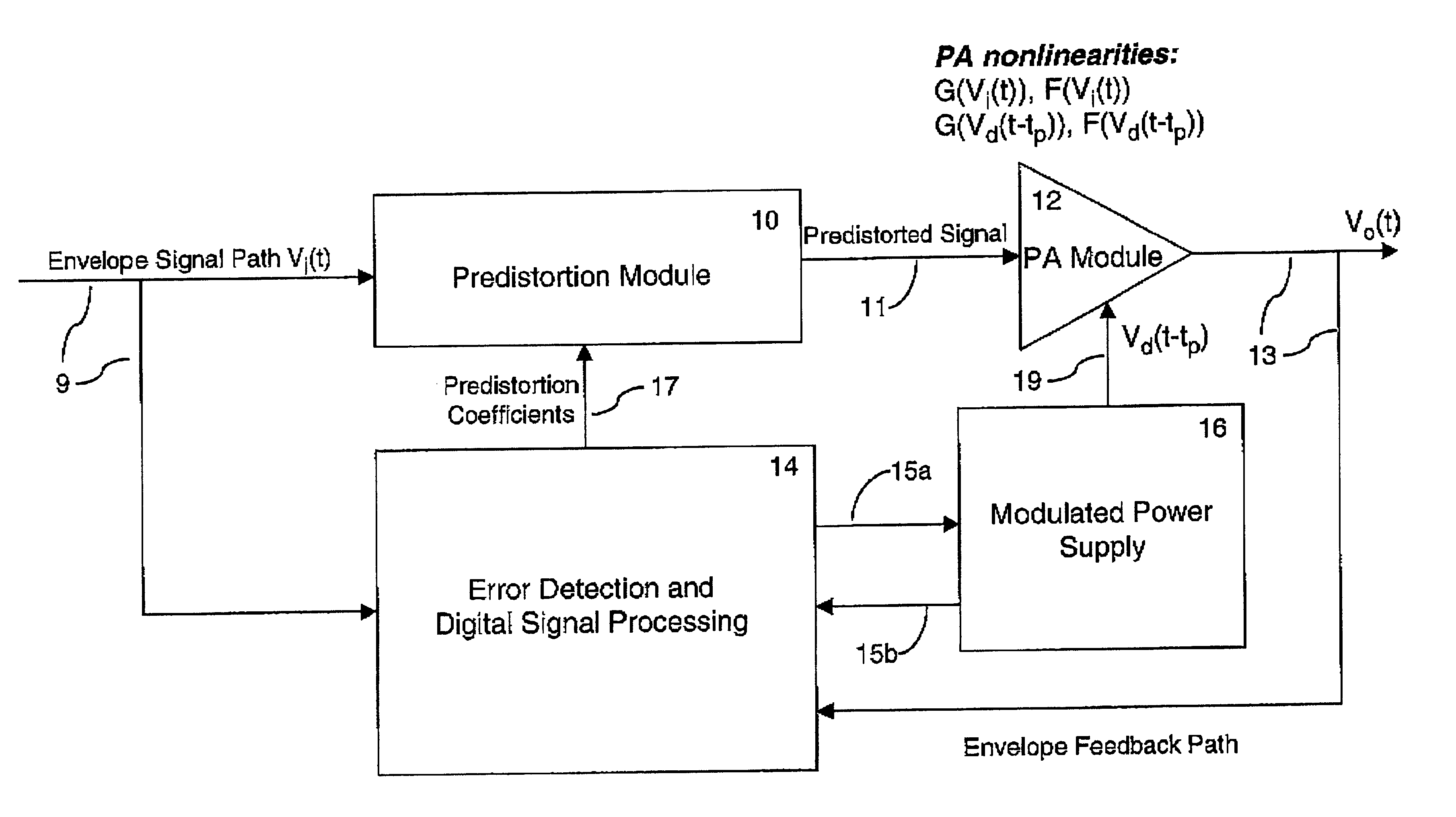
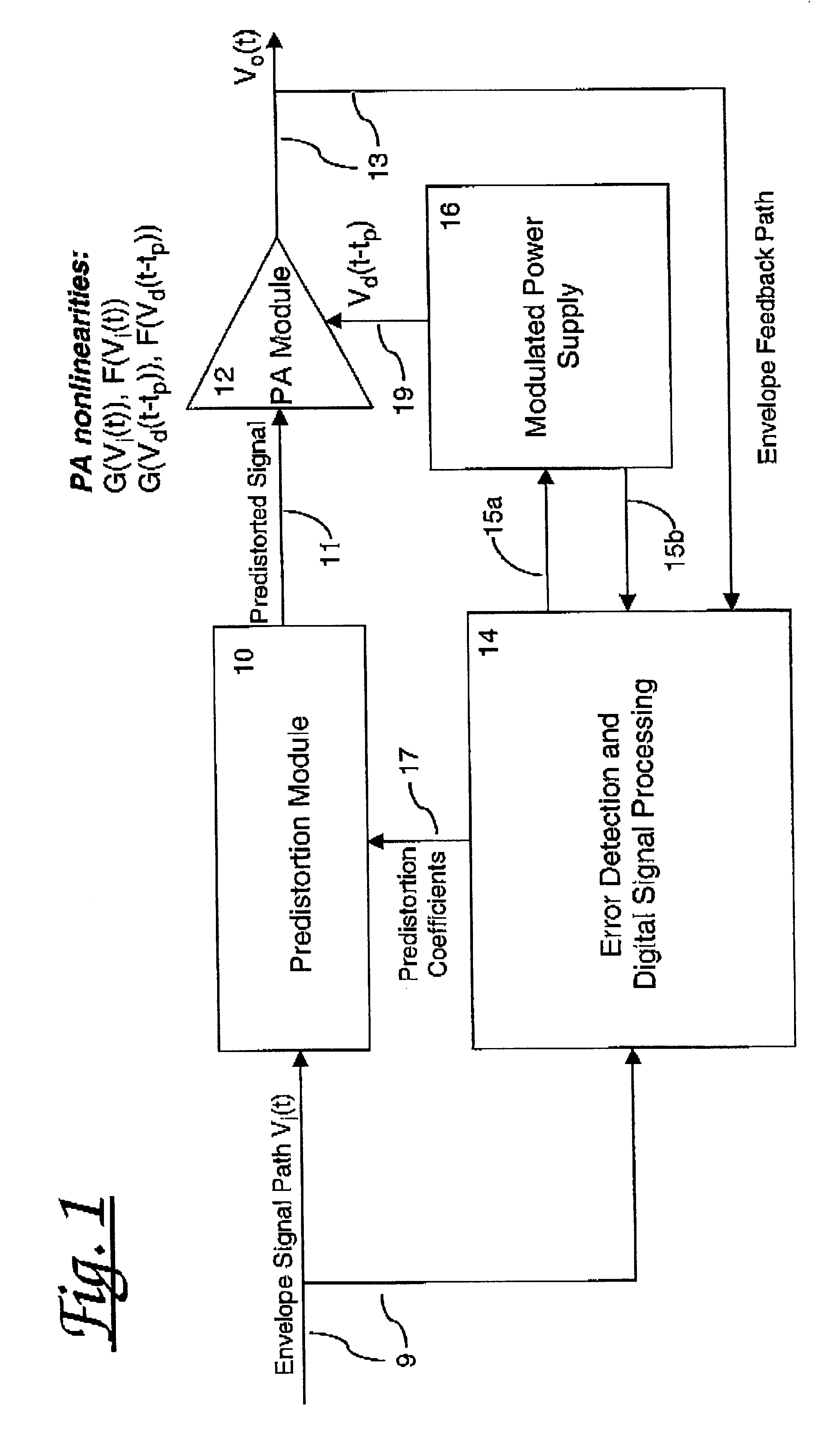
Referring to FIG. 1, there is shown a power amplifier arrangement comprising a predistortion module 10, a power amplifier module 12, an error detection and digital signal processing unit 14, and a modulated power supply 16. In this arrangement an envelope signal path 9 is arranged to provide the envelope signal both to the predistortion module 10 and the error detection and digital signal processing unit 14, the error detection and digital signal processing unit being arranged to provide 17 the predistortion coefficients to the predistortion module. The predistortion module provides 11 a predistorted version of the envelope signal to the power amplifier module 12 which in turn provides 13 an amplified version of the predistorted signal. The modulated power supply 16 provides 19 a power input to the power amplifier module 12, responsive to inputs 15a received from the error detection and digital signal processing unit 14. The error detection and digital signal processing unit 14 rece...


PUM


Abstract

Power amplifier arrangements, methods, and software arranged to receive a power input which is voltage-modulated responsive to at least one control signal representative of the data signal. The data input to the power amplifier is pre-distorted and the resulting power amplification is substantially linear. The arrangement may be used in wireless base station transmitters, but is not limited to such applications. Improved data transmission services are also provided which make use of such power amplifiers.

Description

The present Invention relates to a method and apparatus for power amplification and a system incorporating the same. The invention is particularly, but not exclusively, intended for use in a wireless communications base station.BACKGROUND TO THE INVENTIONKnown wireless communications systems require provision of a high power signal for transmission in order to ensure reception over a suitably wide area. This is achieved by amplifying the data signal to be transmitted, typically at a wireless base station itself, and feeding the resulting amplified signal to the antenna array for wireless transmission. The high amplification levels required for such applications can lead to non-linear distortion of the data signal, which is undesirable. It is therefore highly desirable to use high-performance, linear power amplifier architectures in such applications.A problem with known linear Power Amplifier (PA) technology is that a static back-off, proportional to the signal statistics (Complemen...

Claims


Application Information

Patent Timeline
IPC IPC(8): H03F1/02H03F1/32
CPCH03F1/3247H03F1/0222H03F1/32
Inventor WESSEL, DAVID N
Owner MICROSOFT TECH LICENSING LLC
Why Eureka
Try Eureka