Battery charging and discharging system optimized for high temperature environments

a high temperature environment and battery charging technology, applied in secondary cell servicing/maintenance, greenhouse gas reduction, transportation and packaging, etc., can solve the problems of insufficient alternative sources of electric power, and insufficient charging and discharging conditions

Inactive Publication Date: 2003-12-09
UNILOC 2017 LLC
View PDF6 Cites 39 Cited by
  • Summary
  • Abstract
  • Description
  • Claims
  • Application Information

AI Technical Summary

Problems solved by technology

Although public power grids are highly reliable, these grids are not perfect.
Nor are alternative sources of electric power.
However, the conditions of charging and discharging are not without limitations.
A chemical battery resting in the standby state for long periods of time may degrade due to various factors.
The total power available may be reduced, the terminal voltage may change, and the ability to determine the amount of power available may be compromised.
Electrical energy discharged from the battery can cause thermal problems at high temperature, for both the battery and the adjacent circuitry.
In addition, the components adjacent to the battery conditioning circuit (often a resistive load) may be pushed close to thermal limits due to joule heating of the discharge load at high temperature.
In addition, other heat sources in the vicinity of the battery may affect ambient conditions and raise the operating temperature of the environment.
When a battery is operating at or near its maximum operating temperature, designers are faced with a dilemma.
If the battery charge and discharge currents are maintained at levels normally applied for the lower ranges of expected operating temperatures, the battery life and reliability can be greatly compromised when temperatures become elevated.
On the other hand, if the designer takes a conservative approach, and sets the charge and discharge currents at levels consistent with a reasonable maximum operating temperature, then charge and discharge currents may be so low that the time required to accomplish these operations become unacceptably long.
Each of these alternatives is typically undesirable due to increased cost, greater systems complexity, or reduced reliability, inter alia.

Method used


Image

  • Battery charging and discharging system optimized for high temperature environments
  • Battery charging and discharging system optimized for high temperature environments
  • Battery charging and discharging system optimized for high temperature environments

Examples


Embodiment Construction

Illustrative embodiments and exemplary applications will now be described with reference to the accompanying drawings to disclose the advantageous teachings of the present invention.

While the present invention is described herein with reference to illustrative embodiments for particular applications, it should be understood that the invention is not limited thereto. Those having ordinary skill in the art and access to the teachings provided herein will recognize additional modifications, applications, and embodiments within the scope thereof and additional fields in which the present invention would be of significant utility.

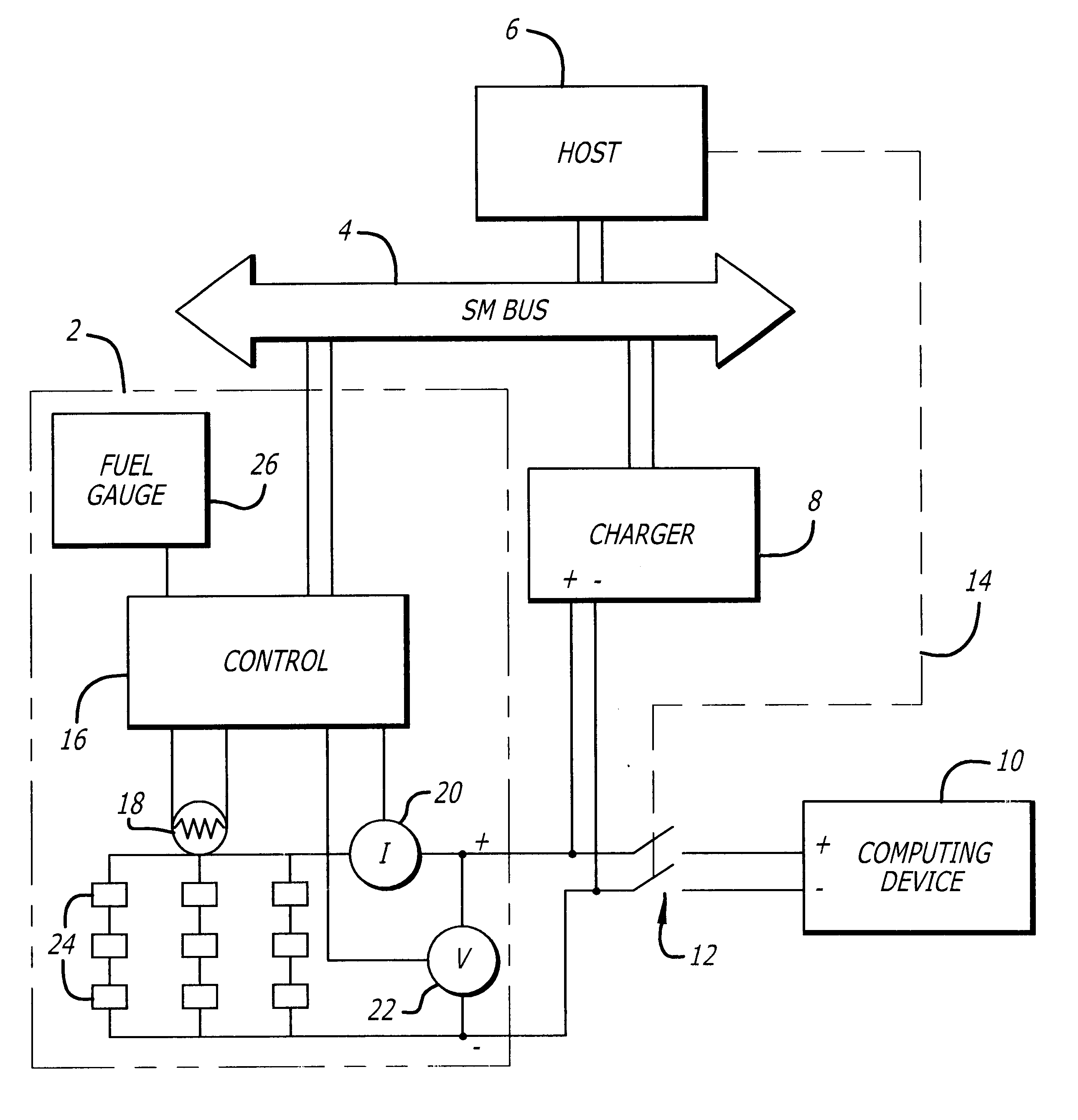
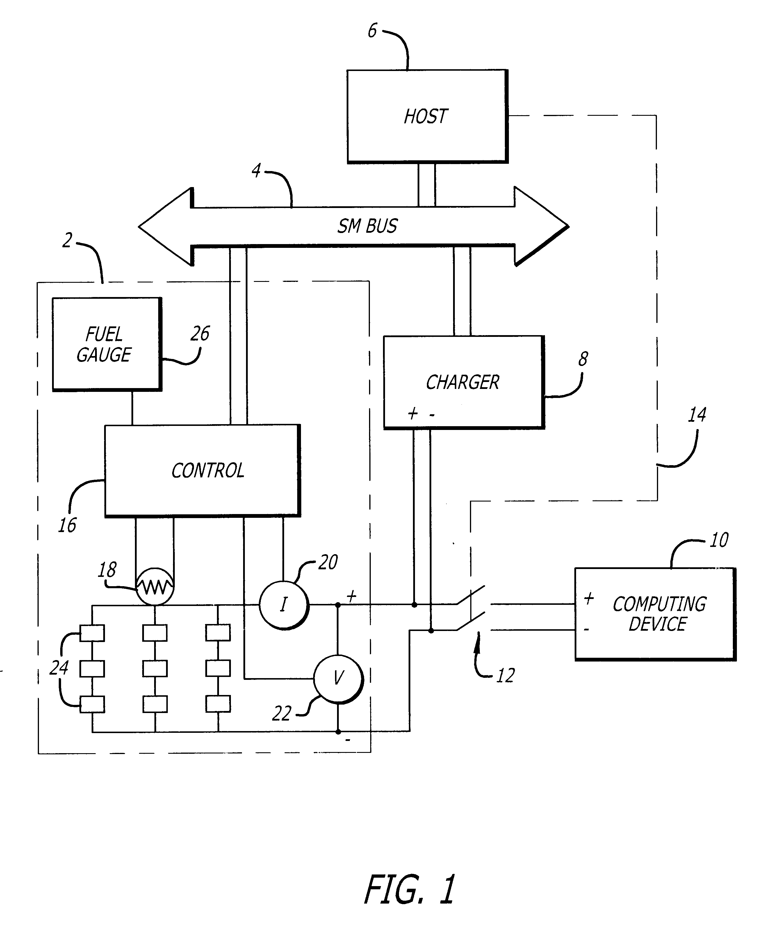
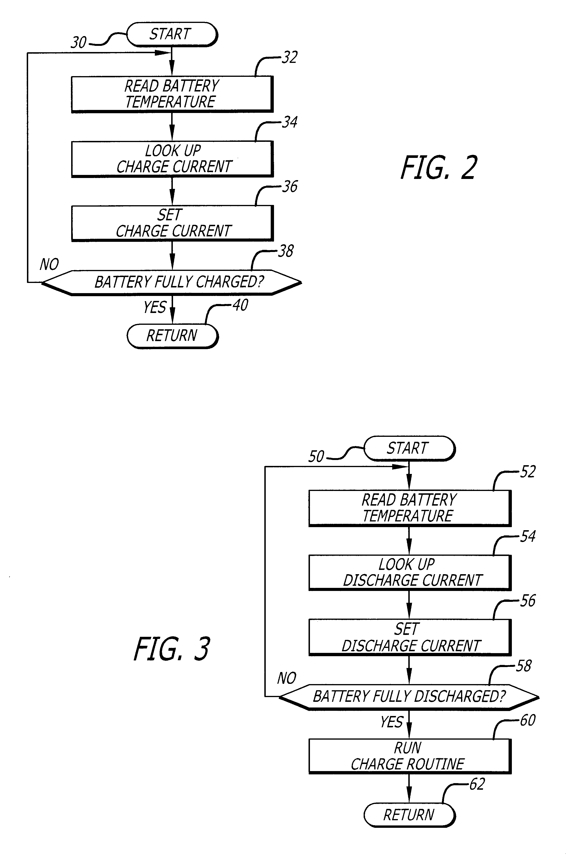
The present invention advantageously utilizes a temperature sensor in combination with a battery charger, or a battery conditioner, to control charging and discharging current flow as a function of the battery temperature. As is understood by those skilled in the art, rechargeable batteries are characterized by a number of operational constraints. Among these ar...


PUM

PropertyMeasurementUnit
terminal voltageaaaaaaaaaa
temperaturesaaaaaaaaaa

Abstract

A method and apparatus for controlling the charge and discharge currents in a battery (2) as a function of temperature. When a battery (2) is charged or discharged in an environment that approaches its design operating temperature extreme, the currents are reduced to limit self-heating of the battery and thus extend the useful operating environment temperature range. A temperature sensor (18) is coupled to a controller (6) to sense the battery (2) temperature. The temperature information is used to set a suitable charging or discharging current (8).

Description

1. Field of the InventionThe present invention relates to apparatus and methods for charging rechargeable batteries. More specifically, the present invention relates to apparatus and method for charging, discharging and recharging rechargeable batteries under adverse thermal conditions.2. Description of the Related ArtReliable electric power sources are needed to meet the continued growth of electric and electronic business, commercial and personal applications. For portable applications, the chemical storage battery is most commonly employed. For fixed location applications, the public power grid is the most common source of electrical power. Also, alternative sources of power are often employed to produce electric power, such as solar-voltaic, thermal, wind, water and other power sources.For many applications, a high degree of reliability is required. Although public power grids are highly reliable, these grids are not perfect. Nor are alternative sources of electric power. Theref...

Claims


Application Information

Patent Timeline
Patent Type & Authority Patents(United States)
IPC IPC(8): H02J7/00H02J7/04H01M10/44H02J7/10
CPCH02J7/0091Y02E70/40Y02B40/90H02J7/007194Y02B40/00Y02E60/10Y02E60/13
Inventor WOLIN, DALECOHEN, EUGENESEVIER, RICHARD G.
Owner UNILOC 2017 LLC
Why Eureka
Try Eureka