Adjustable thermal trip assembly for a circuit breaker

a circuit breaker and trip assembly technology, applied in the direction of circuit-breaking switches, relays, protective switch details, etc., can solve the problem of not always being able to arrang

Inactive Publication Date: 2003-12-09
EATON CORP
View PDF17 Cites 15 Cited by
  • Summary
  • Abstract
  • Description
  • Claims
  • Application Information

AI Technical Summary

Problems solved by technology

Such an arrangement is not always possible, as where the available location for the adjustment mechanism is substantially spaced from the bimetal within the molded housing of the circuit breaker.

Method used


Image

  • Adjustable thermal trip assembly for a circuit breaker
  • Adjustable thermal trip assembly for a circuit breaker
  • Adjustable thermal trip assembly for a circuit breaker

Examples


Embodiment Construction

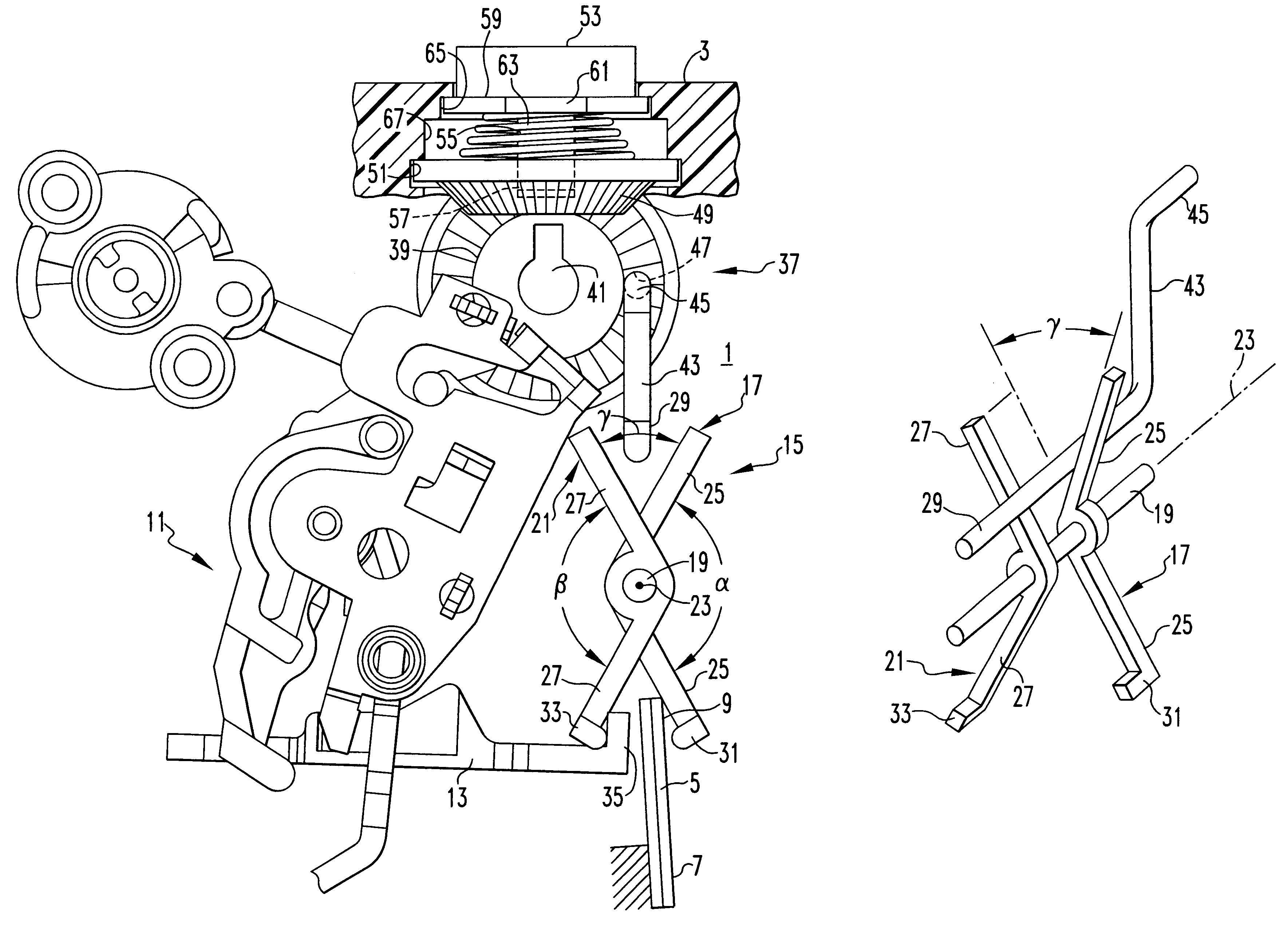
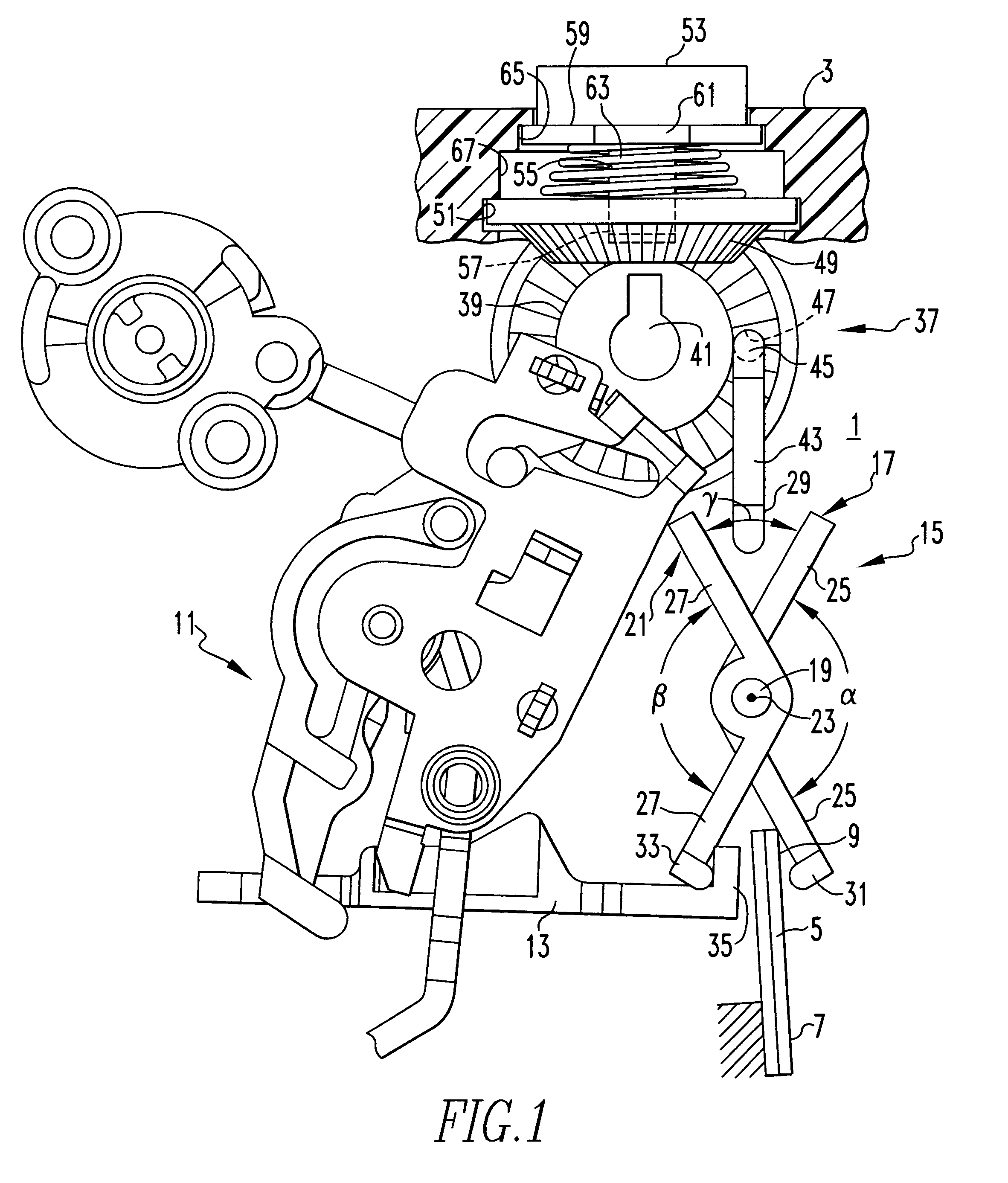
FIG. 1 illustrates an adjustable thermal trip assembly 1 of the invention mounted in the partially shown molded casing 3 of a circuit breaker. The adjustable thermal trip assembly 1 includes a bimetal 5 having a fixed end 7 and a free end 9. As is well known in the art, current in the circuit being protected by the circuit breaker is either passed through the bimetal 5 or through a heater adjacent the bimetal 5. In either case, the bimetal is heated by the load current, which in effect, provides an integration of the load current over time. This heating of the bimetal 5 causes the free end 7 to deflect, to the right as viewed in FIG. 1.

The adjustable thermal trip assembly 1 also includes a trip mechanism 11 which in this case has a trip bar 13. In this known type of trip mechanism 11, the free end 9 of the bimetal 5 couples directly to the trip bar 13 to actuate the trip mechanism 11 when the current / time characteristics of the load current is at a specified value. It is an object o...


PUM


Abstract

The circuit breaker current/time characteristic value at which the bimetal in a thermal trip assembly actuates a trip mechanism is adjusted by an adjustable coupler that includes first and second pivoted members separately rotatable about a common pivot axis. Deflection of the bimetal by an overload current causes rotation of the first pivoted member, which is coupled by a coupling member extending parallel to the common axis into the second pivoted member which rotates to actuate the trip mechanism. A positioner moves the coupling member toward and away from the common pivot axis to adjust the amount of deflection of the bimetal needed to actuate the trip mechanism.

Description

1. Field of the InventionThis invention relates to circuit breakers with a thermal trip assembly, and more particularly to an arrangement for adjustment of the current / time characteristic value at which the assembly responds.2. Background InformationIt is common in the small circuit breakers used for residential and light commercial or industrial applications to utilize a bimetal to provide a delayed trip in response to persistent overload conditions. The heat generated by the overload condition causes the bimetal to deflect until it actuates a trip mechanism to interrupt the current. Thus, it is also known as a thermal trip. In some applications, it is desirable to allow the user to adjust the thermal trip function. Thus, it is known, for instance, to provide a slide which adjusts a gap between the deflecting bimetal and the trip mechanism. Such an arrangement is not always possible, as where the available location for the adjustment mechanism is substantially spaced from the bimet...

Claims


Application Information

Patent Timeline
Patent Type & Authority Patents(United States)
IPC IPC(8): H01H71/00H01H71/74
CPCH01H71/7427H01H2071/7481
Inventor GIBSON, JEFFREY S.
Owner EATON CORP
Why Eureka
Try Eureka