Cover assembly

a technology of cover and assembly, applied in the field of cover assembly, can solve the problems of not being wholly satisfactory, not providing sufficient insulation, and others proving quite expensiv

Inactive Publication Date: 2003-12-16
LINEBACKER UK
View PDF14 Cites 62 Cited by
  • Summary
  • Abstract
  • Description
  • Claims
  • Application Information

AI Technical Summary

Problems solved by technology

A number of arrangements have been proposed to temporarily cover ice, but in general these have not been wholly satisfactory.
For example, some do not provide sufficient insulation, and others have proved quite expensive.

Method used


Image

  • Cover assembly
  • Cover assembly
  • Cover assembly

Examples


Embodiment Construction

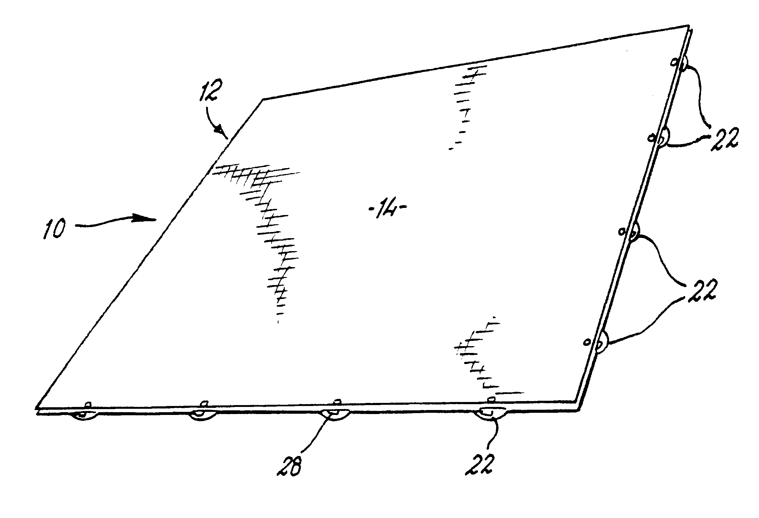
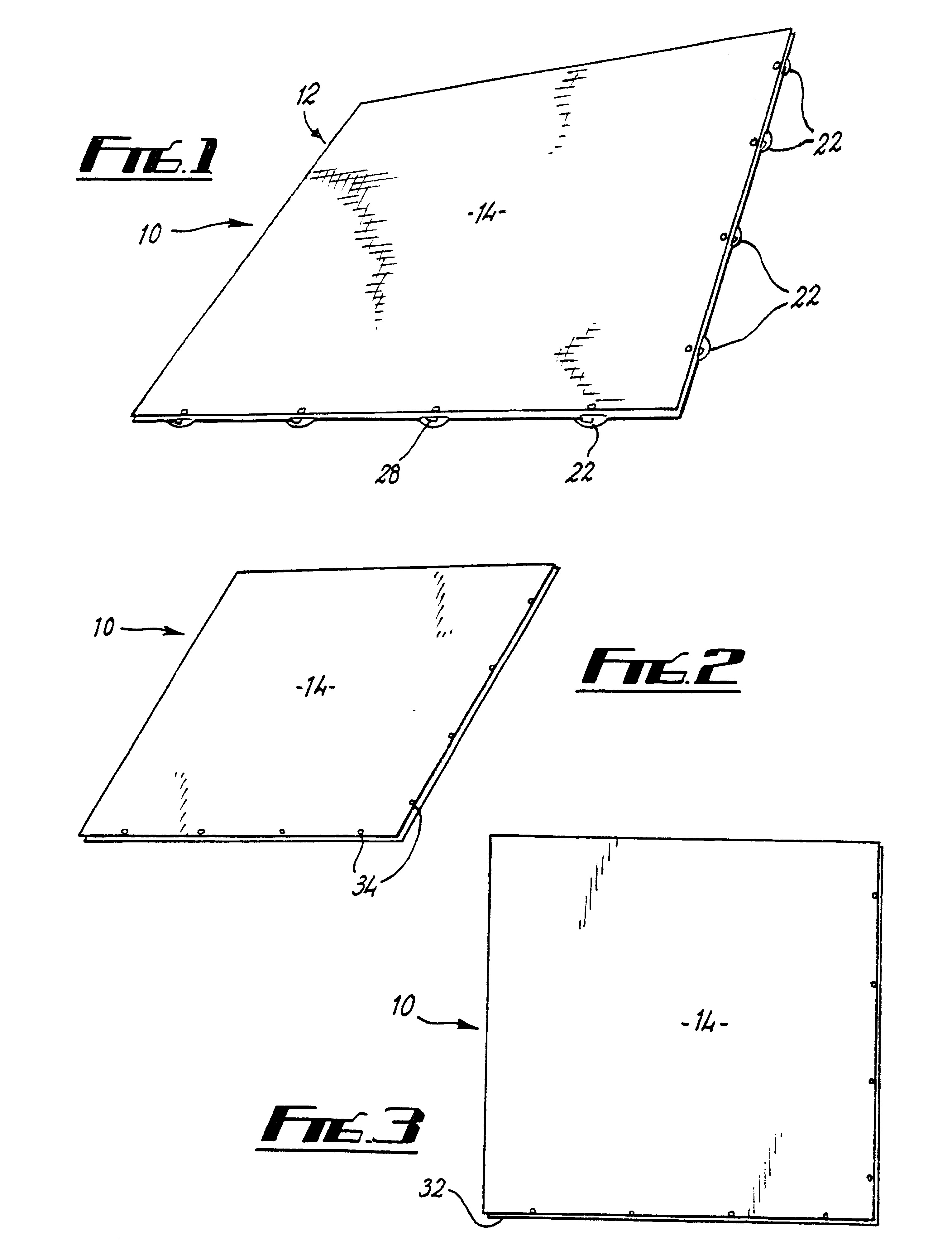
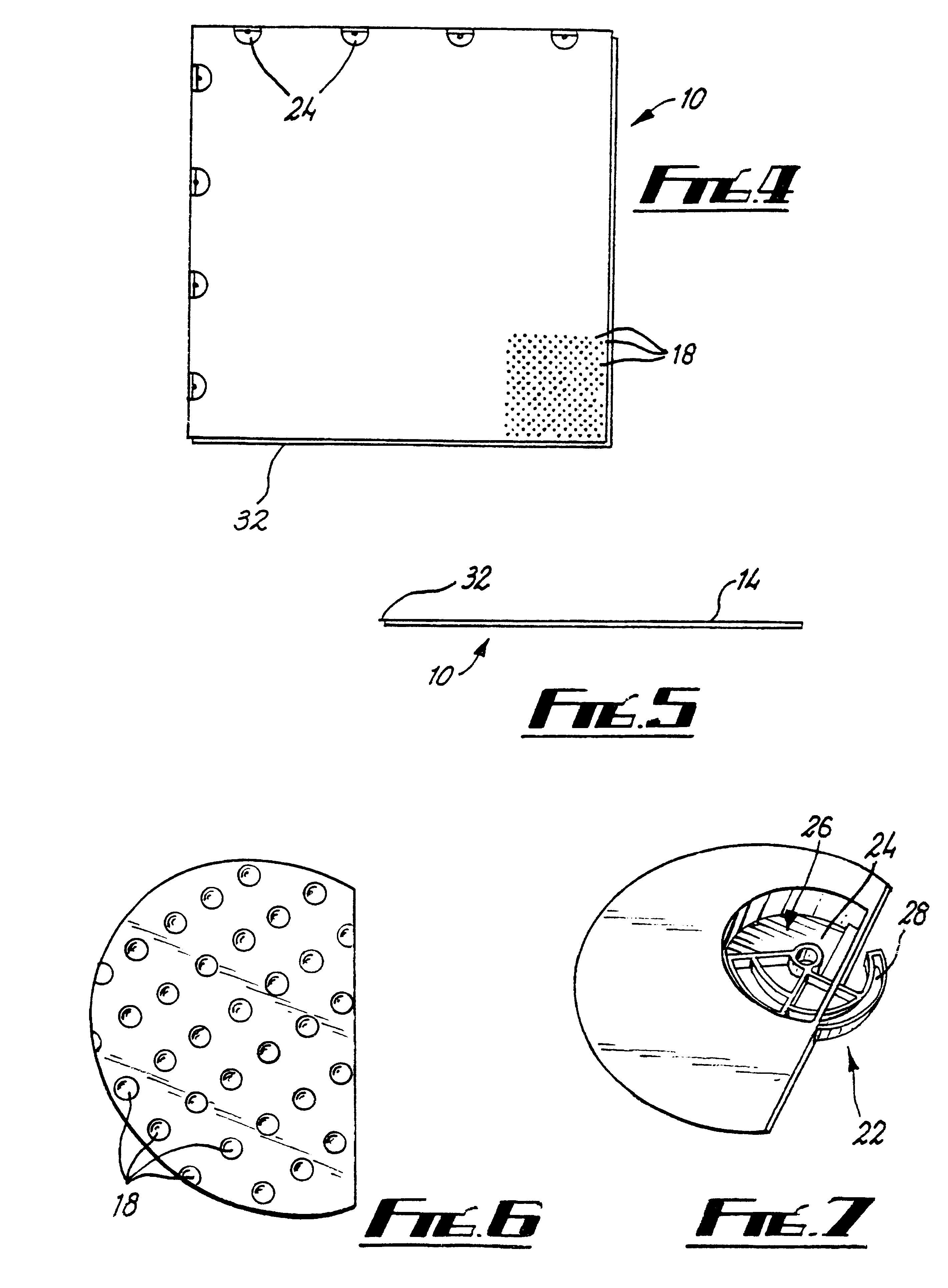
The Drawings show a component 10 usable in a cover assembly according to the invention suitable for instance for temporarily covering an ice rink. The component 10 has a generally square configuration with an upper part 12 defining an upper surface 14 which can support people or other items thereon. The surface 14 may have any suitable formations (not shown) thereon to aid the grip of people walking on the component 10. Such formations may be in the form of raised chevron shaped formations to create a non-slip surface.

The component 10 also has a lower part 16 which is generally planar apart from a plurality of spaced upwardly extending frusto conical hollow projections 18 which extend to meet and support the upper part 12, and a number of locking recesses (see below). The upper and lower parts 12,18 define a gap 20 therebetween. Side walls are also provided for the component 10 such that the gap 20 is substantially sealed apart from a small number of vent holes (not shown) which are...


PUM


Abstract

A cover assembly for temporarily covering areas such as an ice rink, to support people or other items thereon. The assembly comprises a number of components (10) which can be engaged with other such components (10) placed adjacent thereto-on the surface to be covered. The components include upper and lower parts (12, 16) with a gap (20) being provided between such parts to provide insulation from the underlying area. Adjacent components (10) are retained together by locking means (22) which are provided on two adjacent sides of each component (10). and are selectively engageable in recesses (32) on adjacent components (10).

Description

TECHNICAL FIELD AND BACKGROUND OF THE INVENTIONThis application is a national stage application, according to Chapter II of the Patent Cooperation Treaty. This application claims the priority date of Apr. 6, 1999 for Great Britain Patent Application No. 9907607.7.This invention concerns a cover assembly, and particularly but not exclusively an area for covering an area of ice such as for example at an ice rink.To make full use of venues such as ice rinks it is often desirable for the ice to be covered to permit activities to take place other than on ice. Such activities may comprise other sports such as boxing or basketball, or concerts or other performances. A number of arrangements have been proposed to temporarily cover ice, but in general these have not been wholly satisfactory. For example, some do not provide sufficient insulation, and others have proved quite expensive.According to the present invention there is provided a cover assembly, the assembly comprising a plurality o...

Claims


Application Information

Patent Timeline
Patent Type & Authority Patents(United States)
IPC IPC(8): A63C19/00A63C19/12
CPCA63C19/12
Inventor ELSE, ROBERT ARTHUR
Owner LINEBACKER UK
Why Eureka
Try Eureka