Error concealment in relation to decoding of encoded acoustic signals

a technology of encoded acoustic signals and error concealment, applied in the field of concealment of errors in decoding acoustic signals, can solve problems such as power level limitation of the first correctly received frame after receiving one or more damaged frames, and codecs operating under adverse channel conditions

Inactive Publication Date: 2003-12-16
TELEFON AB LM ERICSSON (PUBL)
View PDF19 Cites 85 Cited by
  • Summary
  • Abstract
  • Description
  • Claims
  • Application Information

AI Technical Summary

Benefits of technology

The proposed explicit generation of a reconstructed spectrum as a result of lost or received damaged data ensures spectrally smooth transitions between periods of received undamaged data and periods of received damaged data. This, in turn, provides an enhanced perceived sound quality of the decoded signal, particularly for advanced broadband codecs, for instance, involving ACELP-coding schemes.

Problems solved by technology

Particularly in mobile applications, the codecs occasionally operate under adverse channel conditions.
One consequence of such non-optimal transmission conditions is that encoded bits representing the speech signal are corrupted or lost somewhere between the transmitter and the receiver.
If, however, several consecutive speech codec frames are lost or damaged various muting techniques are applied, which may involve repetition of gain parameters with decaying factors and repetition of LPC-parameters moved towards their long-term averages.
Furthermore, the power level of the first correctly received frame after reception of one or more damaged frames may be limited to the power level of the latest correctly received frame before reception of the damaged frame(s).
However, in case of a lost frame the filtering coefficients of the post filter are not updated.
However, this is not always the case.
A mere repetition of spectral parameters from a latest received undamaged speech codec frame could thus result in abrupt changes in the spectrum of the decoded acoustic signal, which, of course, means that a low sound quality is experienced.
Particularly, wide-band speech codecs operating according to the CELP coding paradigm have proven to suffer from the above problems, because in these codecs the spectral shape of the synthesis filter excitation may vary even more dramatically from one speech codec frame to another.

Method used


Image

  • Error concealment in relation to decoding of encoded acoustic signals
  • Error concealment in relation to decoding of encoded acoustic signals
  • Error concealment in relation to decoding of encoded acoustic signals

Examples


Embodiment Construction

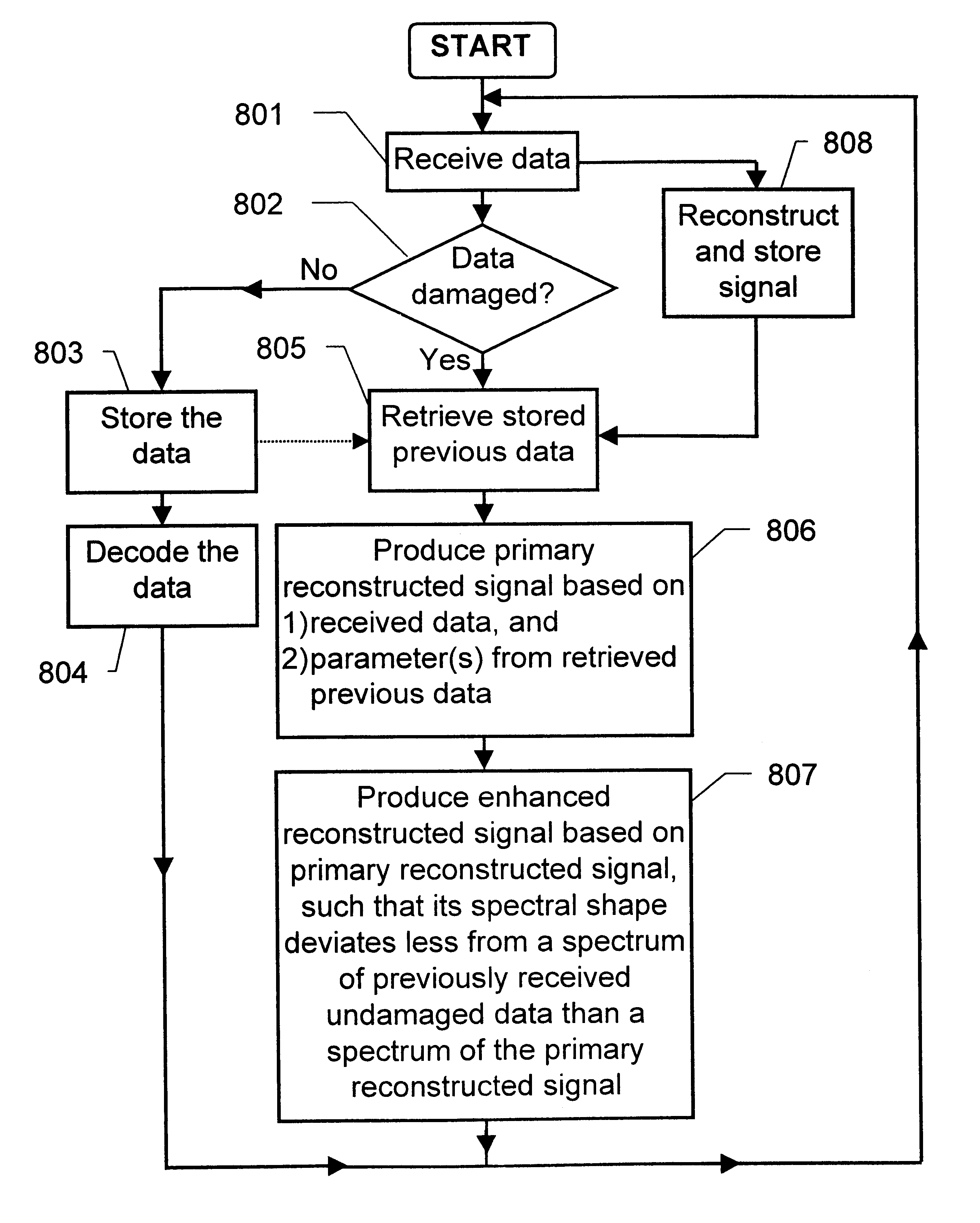
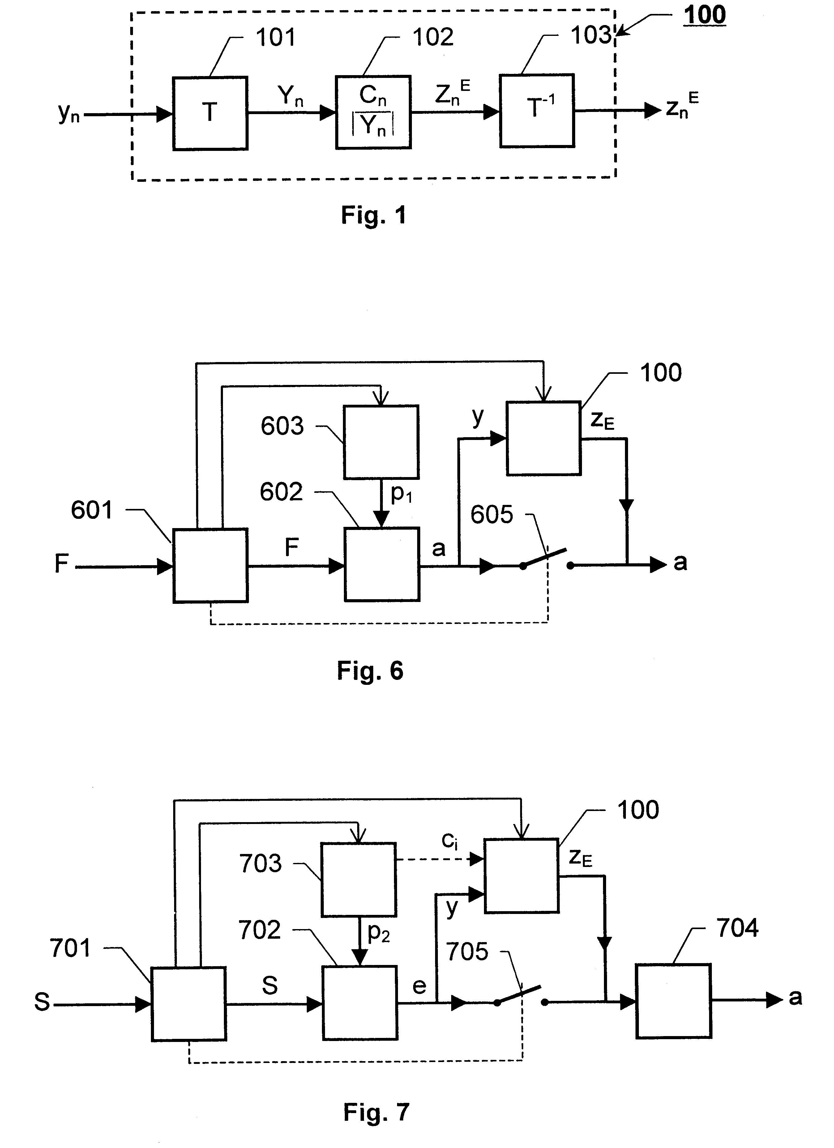
FIG. 1 shows a block diagram over an error concealment unit according to the invention. The object of the error concealment unit 100 is to produce an enhanced signal Z.sub.n.sup.E decoded from received data in case the received data is damaged or lost. The enhanced decoded signal Z.sub.n.sup.E either represents a parameter of a speech signal, such as an excitation parameter, or the enhanced decoded signal Z.sub.n.sup.E itself is an acoustic signal. The unit 100 includes a first transformer 101, which receives a primary reconstructed signal y.sub.n being derived from the received data. The primary reconstructed signal y.sub.n is regarded as a signal in the time domain and the first transformer 101 regularly produces a primary reconstructed frequency transform Y.sub.n of a latest received time segment of the primary reconstructed signal y.sub.n in the form of a first spectrum. Typically, each segment corresponds to a signal frame of the received signal.

The first spectrum Y.sub.n is fo...


PUM


Abstract

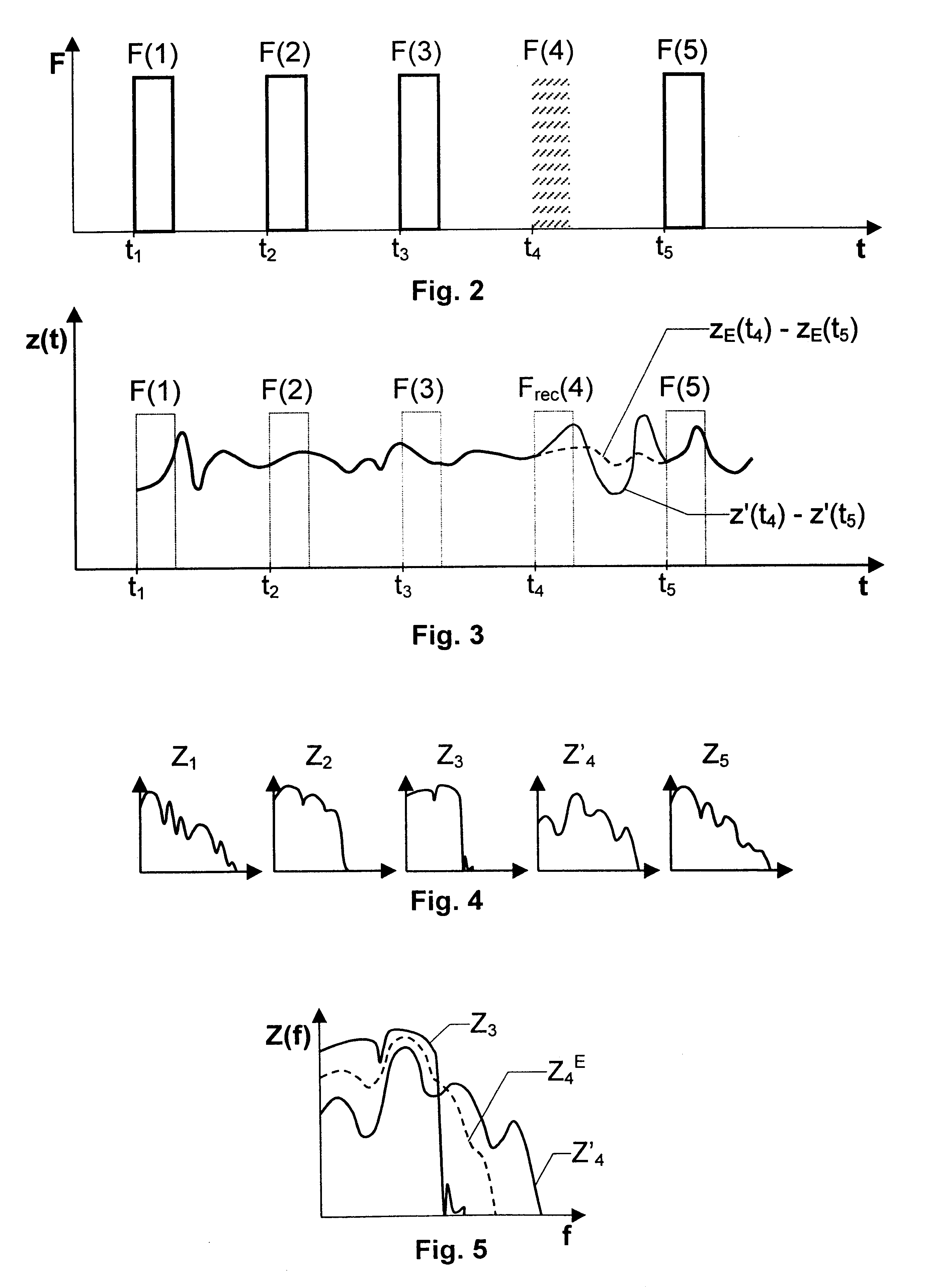
The present invention relates to the concealment of errors in decoded acoustic signals caused by encoded data representing the acoustic signals being partially lost or damaged during transmission over a transmission medium. In case of lost data or received damaged data a secondary reconstructed signal is produced on basis of a primary reconstructed signal. This signal has a spectrally adjusted spectrum (Z4<E>), such that it deviates less with respect spectral shape from a spectrum (Z3) of a previously reconstructed signal produced from previously received data than a spectrum (Z'4) of the primary reconstructed signal.

Description

THE BACKGROUND OF THE INVENTION AND PRIOR ARTThe present invention relates generally to the concealment of errors in decoded acoustic signals caused by encoded data representing the acoustic signals being partially lost or damaged. More particularly the invention relates to a method of receiving data in the form of encoded information from a transmission medium and an error concealment unit according to the preambles of claims 1 and 39 respectively. The invention also relates to decoders for generating an acoustic signal from received data in the form of encoded information according to the preambles of claims 41 and 42 respectively, a computer program according to claim 37 and a computer readable medium according to claim 38.There are many different applications for audio and speech codecs (codec=coder and decoder). Encoding and decoding schemes are, for instance, used for bit-rate efficient transmission of acoustic signals in fixed and mobile communications systems and in videocon...

Claims


Application Information

Patent Timeline
Patent Type & Authority Patents(United States)
IPC IPC(8): G10L19/00G10L19/005H04L1/00
CPCG10L19/005
Inventor BRUHN, STEFAN
Owner TELEFON AB LM ERICSSON (PUBL)
Why Eureka
Try Eureka