Tool including a tool bit and a handle

a tool and handle technology, applied in the field of tools, can solve the problems of bulky handles and heavy carrying, and achieve the effect of improving the carrying capacity and reducing the burden

Inactive Publication Date: 2004-04-27
LIOU MOU TANG
View PDF6 Cites 34 Cited by
  • Summary
  • Abstract
  • Description
  • Claims
  • Application Information

AI Technical Summary

Problems solved by technology

The handles are bulky and heavy to carry.

Method used


Image

  • Tool including a tool bit and a handle
  • Tool including a tool bit and a handle
  • Tool including a tool bit and a handle

Examples


Embodiment Construction

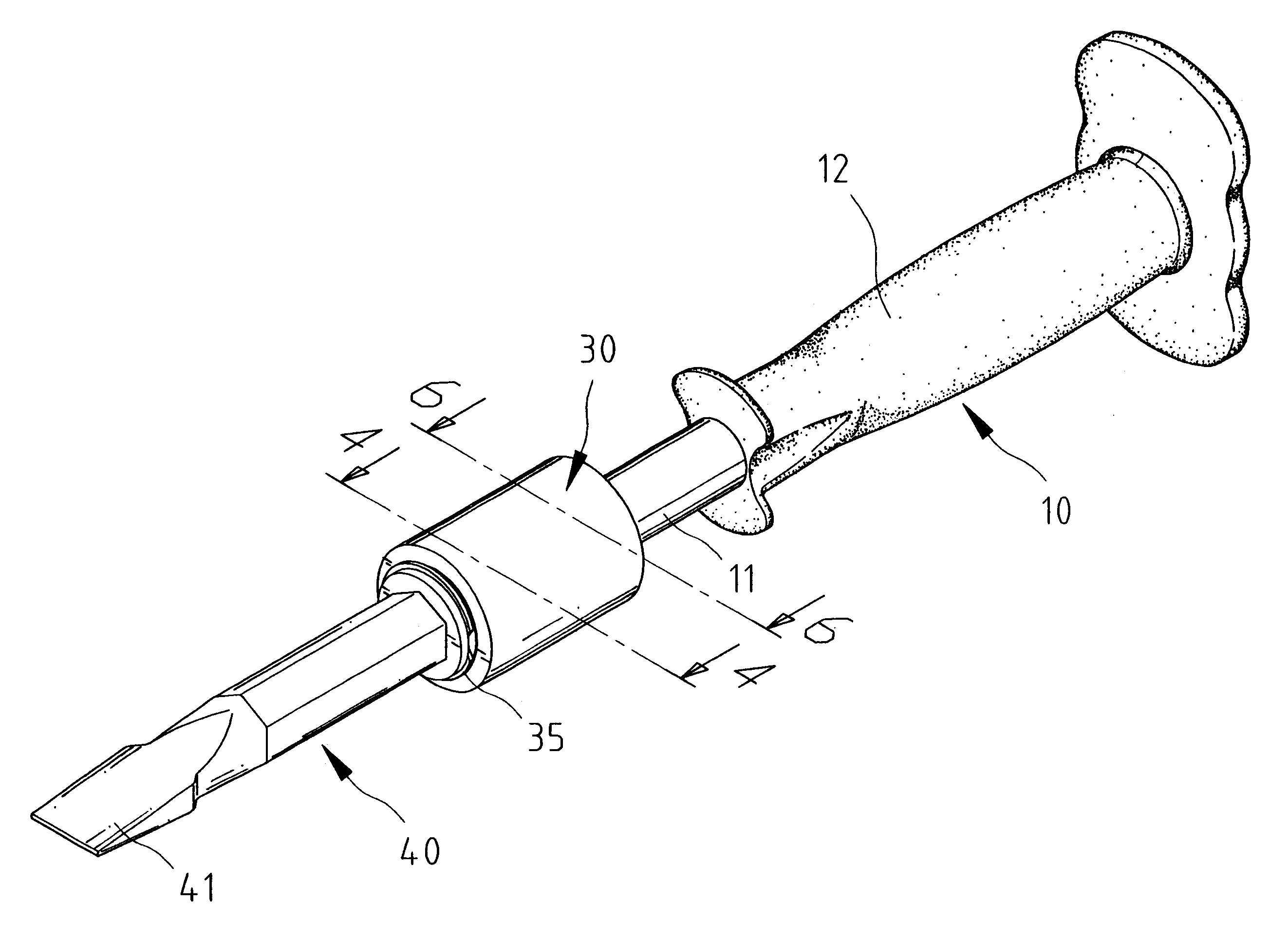
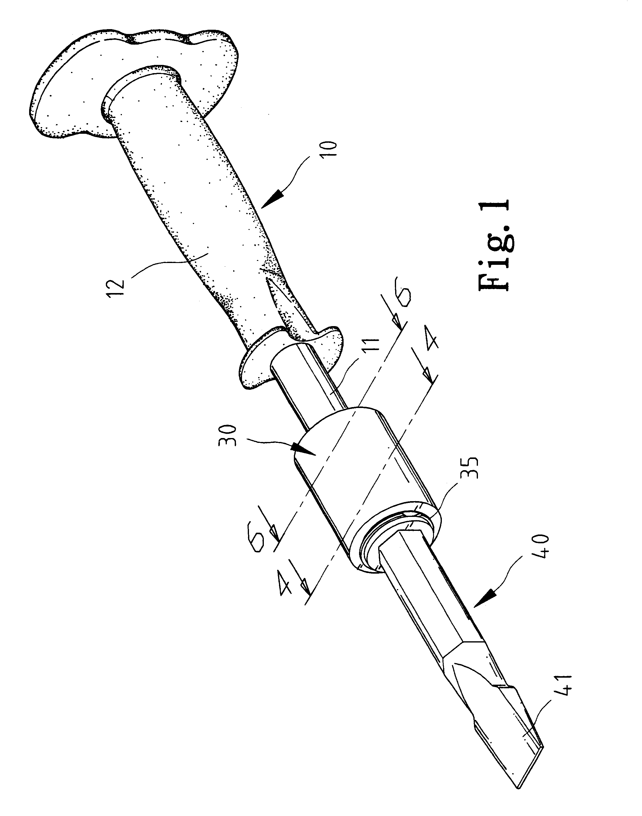
Referring to FIG. 1, according to the present invention, a tool includes a tool bit 40 and a handle 10 for releasable engagement with the tool bit 40.

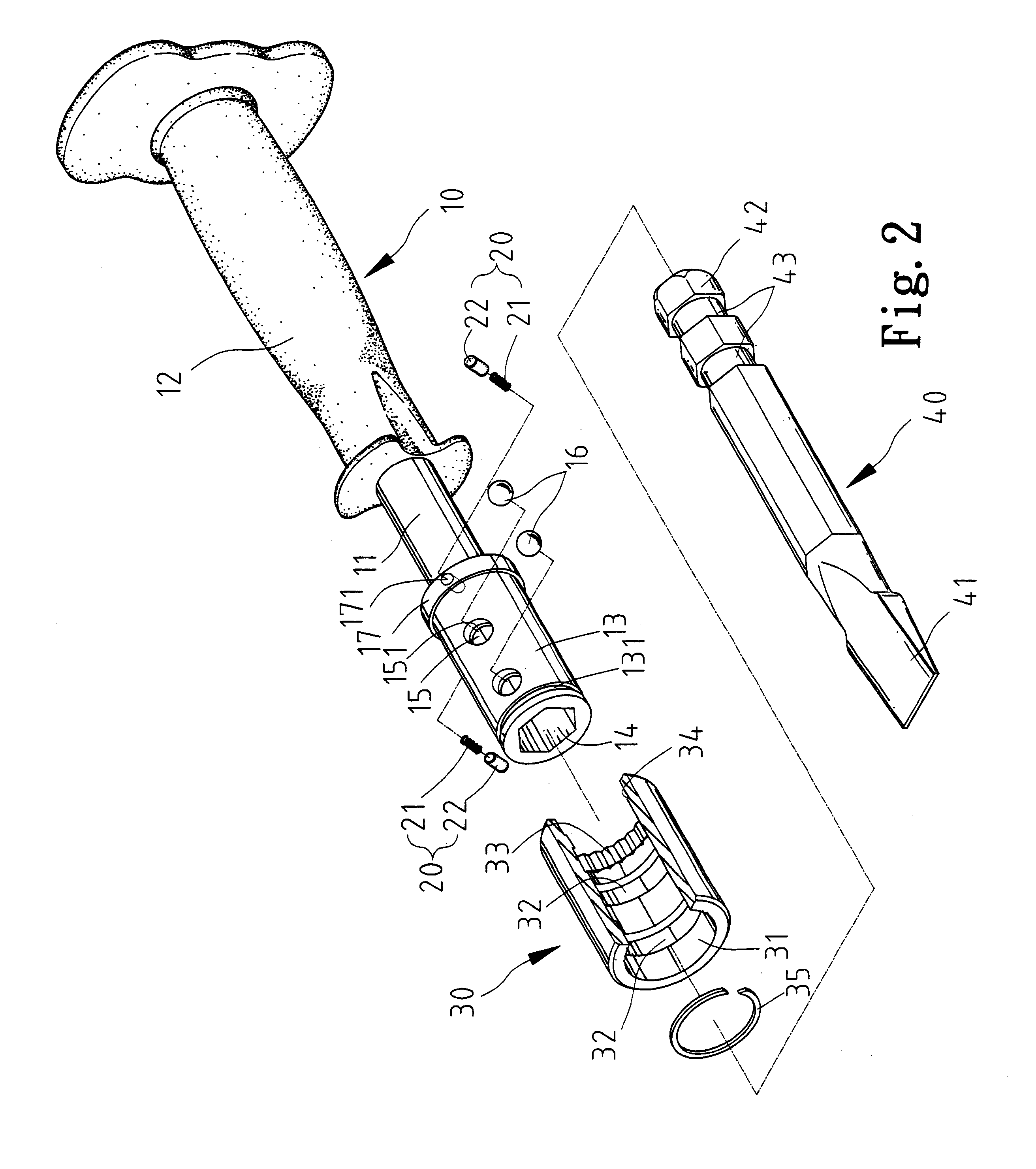
Referring to FIG. 2, the handle 10 includes a shaft 11, a grip 12 mounted on an end of the shaft 11 and a socket 13 formed at an opposite end of the shaft 11.

The socket 13 includes a cavity 14 defined therein and two holes 15 communicated with the cavity 14 are defined. Each of the holes 15 includes an internal end at an internal face of the socket 13 and an external end at an external face of the socket 13. An annular stop 151 is formed on the wall of each of the holes 15 at the internal end. An annular groove 131 is defined in the external face of the socket 13 near an end. Two recesses 171 are defined in an annular rib 17 formed on the external face of the socket 13 at an opposite end .

As defining a hole, the sleeve 30 includes an internal face 31. Two annular grooves are defined in the internal face 31. Each of the annular grooves ...


PUM


Abstract

A tool includes a tool bit and a handle for releasable engagement with the tool bit. The tool bit includes an insert formed thereon. The handle includes a socket formed thereon. The socket includes a cavity defined therein for receiving the insert and at least one hole communicated with the cavity. The at least one hole includes an internal end and an external end larger than the internal end. The at least one annular groove defined in the insert is aligned with the at least one hole when the insert is inserted in the socket. At least one ball is received in the at least one hole. A sleeve includes an internal face and at least one cam surface formed on the internal face thereof. The sleeve is rotationally mounted on the socket between a first position and a second position. In the first position, the at least one cam surface allows complete removal of the at least one ball from the cavity. In the second position, the at least one cam surface pushes the at least one ball into the cavity.

Description

BACKGROUND OF INVENTION1. Field of InventionThe present invention relates to a tool including a tool bit and a handle for releasable engagement with the tool bit.2. Related Prior ArtA conventional hand tool includes a tool bit secured to or integrated with a handle. Therefore, a user has to carry many handles and corresponding tool bits if wanting to do various types of work. The handles are bulky and heavy to carry.There have been devised various hand tools that each include a tool bit engaged with a handle in a releasable manner. Generally, such a tool bit includes an insert, and such a handle includes a socket for receiving the insert. A locking device is used to lock the insert in the socket.SUMMARY OF INVENTIONIt is an objective of the present invention to provide a tool including a tool bit and a handle engaged with the tool bit in a releasable manner.According to the present invention, a tool includes a tool bit and a handle for releasable engagement with the tool bit. The to...

Claims


Application Information

Patent Timeline
Patent Type & Authority Patents(United States)
IPC IPC(8): B25B23/00B25D3/00B25G3/26B25G3/00
CPCB25B23/0035B25D3/00B25G3/26B25D2250/011B25D2250/105
Inventor LIOU, MOU-TANG
Owner LIOU MOU TANG
Why Eureka
Try Eureka