
Active forceps

a technology of active forceps and forceps, which is applied in the field of active forceps, can solve the problems of poor stiffness and durability, inability to eviscerate, and weak transmission, and achieves the effect of improving the strength and durability of the forceps, and improving the safety of us

Inactive Publication Date: 2004-09-21
TOKYO UNIV OF THE
View PDF6 Cites 838 Cited by
  • Summary
  • Abstract
  • Description
  • Claims
  • Application Information

AI Technical Summary

Benefits of technology

"The present invention provides an active forceps that can be used for less invasive surgical operations with strong force requirements at the forceps tip, such as evisceration. The forceps is downsized and has a higher stiffness and durability compared to wire-driven forceps. It includes a forceps tip part with a tip supporting member and a plurality of tip side advancing and retreating members, and a bottom frame with a plurality of bottom side advancing and retreating members. The forceps tip can be moved by actuating the tip side advancing and retreating members, which are integrally coupled to the bottom side advancing and retreating members. The forceps tip can change orientation by efficiently transmitting a driving force to the forceps tip via the link mechanism. The forceps bottom part may also have a rotation actuating means to rotate the bottom frame around a predetermined axis."

Problems solved by technology

However, a wire-driven forceps has been used for endoscopic operations such as suture of blood vessels with no requirements of strong force, since it is difficult to transmit a strong force to the tips of the forceps even with a high driving force of the actuator, due to the poor stiffness and durability of wire likely to be stretched or cut.
Therefore, the above conventional wire-driven active forceps have been inappropriate for evisceration.

Method used


Image

  • Active forceps
  • Active forceps
  • Active forceps

Examples


Embodiment Construction

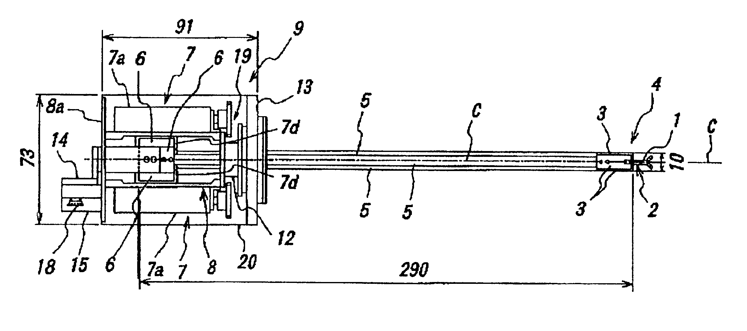
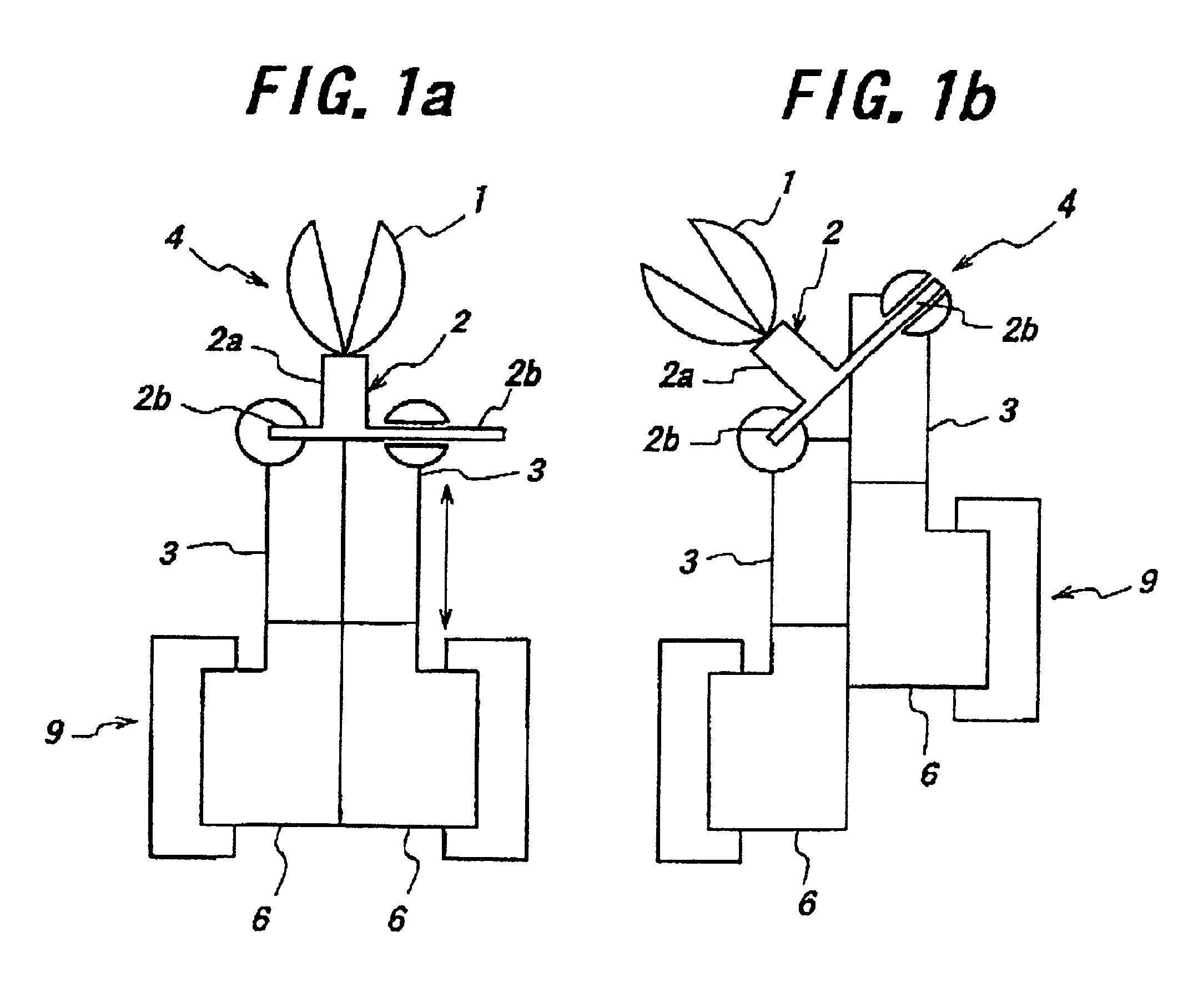
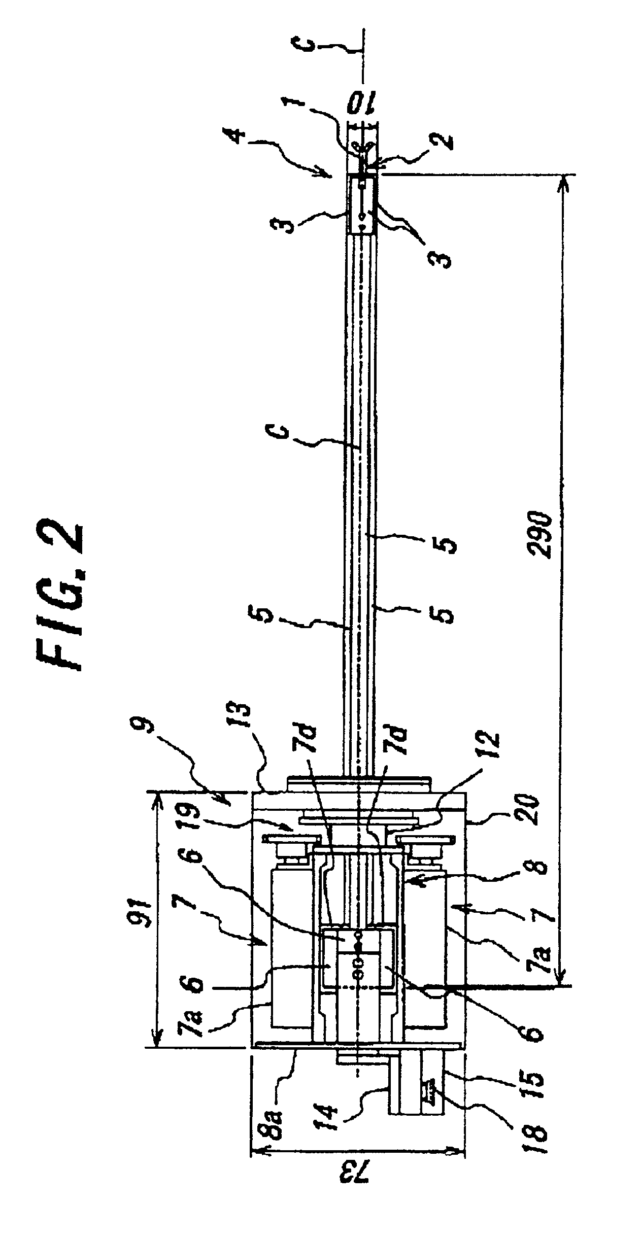
Now, a preferred embodiment of the present invention will be explained in detail hereafter referring to drawings. In FIGS. 2 to 6(a), (b), the same parts as in FIG. 1 are denoted with the same reference numerals or symbols.

An active forceps of this embodiment comprises a forceps tip part 4 having, as shown in FIGS. 3 and 4, a tip supporting member 2 with a tubular center section 2a to support forceps tip 1 opened and closed by manipulation with wire, and three arms 2b laterally projected from the center section 2a, and having three up side advancing and retreating members 3 connected at a front end oscillatably and slidably with three arms 2b of the tip supporting member 2 respectively via ball 10 constituting a ball joint. The three tip side advancing and retreating members 3 here are fitted into one another slidably toward front and rear ends, while, in an intersecting direction, coupled to one another relatively movably to the directions toward front and rear ends by inseparably ...


PUM


Abstract

Endoscopic surgical operation such as evisceration has been so far hardly achieved by a medical robot, since it requires high power. The present invention provides a downsized high-flexibility active forceps to enable such an operation, without needing a large space for manipulation to target a limited operative area. An active forceps of the present invention comprises: a tip forceps part 4 having, a tip supporting member 2 to support a forceps tip 1 at a center section 2a with a plurality of arms 2b laterally projected therefrom, and a plurality of tip side advancing and retreating members 3 connected at a front end with the plurality of arms respectively oscillatable while connected to one another relatively movable in directions toward front and rear ends; and a forceps bottom part 9 having, a plurality of bottom side advancing and retreating members 6 each integrally coupled to the plurality of tip side advancing and retreating members 3, while connected to one another relatively movable indirections toward front and rear ends to constitute a link mechanism together with the tip side advancing and retreating members 3 and the tip supporting member 2, and a bottom frame 8 provided with forward and backward actuating means 7 for moving relatively to one another the bottom side advancing and retreating members 6 in directions toward front and rear ends.

Description

1. Field of the InventionThe present invention relates to an active forceps used for less invasive surgical operation and more particularly to a downsized high-stiffness active forceps.2. Related ArtIn the prior art, most of the active forceps in master-slave-type robot for less invasive surgical operation (particularly for endoscopic surgical operation) has been wire-driven, since it is relatively easy by driving it with wire to realize a downsized mechanism changing orientation by a driving force transmitted from an actuator positioned at the bottom to the tips of forceps.However, a wire-driven forceps has been used for endoscopic operations such as suture of blood vessels with no requirements of strong force, since it is difficult to transmit a strong force to the tips of the forceps even with a high driving force of the actuator, due to the poor stiffness and durability of wire likely to be stretched or cut.When an active forceps is used for evisceration, for example, an actuato...

Claims


Application Information

Patent Timeline
Patent Type & Authority Patents(United States)
IPC IPC(8): A61B17/28A61B19/00A61B17/00
CPCA61B17/29A61B19/2203A61B2017/00398A61B2017/2927A61B2019/2226A61B2019/2249A61B34/30A61B34/72A61B2034/304A61B17/28
Inventor NAKAMURA, YOSHIHIKOOKADA, MASAFUMIWATABE, KOICHI
Owner TOKYO UNIV OF THE
Learn More