
Fence bracket system and fence system using the fence bracket system

a technology of fence brackets and bracket systems, which is applied in the field of fence bracket systems and fence systems, can solve the problems that none of the numerous conventional bracket systems can produce a very strong fen

Inactive Publication Date: 2004-10-12
PRETA JOHN
View PDF70 Cites 104 Cited by
  • Summary
  • Abstract
  • Description
  • Claims
  • Application Information

AI Technical Summary

Benefits of technology

"The invention is a fence bracket system that allows for a strong, easily adjustable, and repairable fence. The system includes a post bracket, rail brackets, and fasteners that can be used to assemble fences. The bracket system is efficient, easy to install, and can be used to assemble fences on-site. The technical effects of the invention include a stronger fence that is easier to assemble and repair, as well as a more efficient and cost-effective method for assembling fences."

Problems solved by technology

However, none of the numerous conventional bracket systems are able to produce a fence that is very strong, while being easily adjustable and / or repairable, easy and inexpensive to make, and which can be used to efficiently assemble a fence.

Method used


Image

  • Fence bracket system and fence system using the fence bracket system
  • Fence bracket system and fence system using the fence bracket system
  • Fence bracket system and fence system using the fence bracket system

Examples


first embodiment

FIG. 6 illustrates the layout of a piece of sheet metal which can be used to form first embodiment rail bracket RB. The various features are not drawn to scale. However, the general arrangement or positions of the bend lines and holes are shown to illustrate their general locations. The sheet metal piece has a generally rectangular shape with an upper or top edge having tab portions which extend therefrom and a lower or bottom edge. To form the generally rectangular shaped rail bracket RB shown in FIGS. 8 and 9, the sheet metal piece has five sections which are defined by four bend lines BL which extend from the top edge to the bottom edge. Beginning from the left side, left back section "bp" is defined by the left side edge of the rectangular sheet metal piece and the first bend-line BL. Left section or left side back panel "bp" will form approximately 1 / 2 of the bottom wall of the rail bracket RB. As a result, the length of this section "bp" (measured between left edge and the fir...

second embodiment

FIG. 27 illustrates another embodiment of a bracket system. This embodiment shown a post bracket PB6 which can be made in a similar manner to that already described with regard to FIGS. 14-17, except that the position of the tabs T1-T4 correspond to a position, with respect to the post P and rails R, similar to that shown in FIGS. 25-26. This bracket system embodiment uses the second embodiment rail brackets RB' shown in, e.g., FIGS. 22-24 and the bolts B' shown in FIG. 26.

FIG. 28 illustrates another embodiment of a bracket system. This embodiment shown a post bracket PB4 which can be made in a similar manner to that already described with regard to FIGS. 18-21. This bracket system embodiment uses the second embodiment rail brackets RB' shown in, e.g., FIGS. 22-24 as well as the bolts B and spacers CW shown in FIG. 22.

FIG. 29 illustrates still another embodiment of a bracket system. This embodiment shown a post bracket PB1 which can be made in a similar manner to that already descri...

third embodiment

FIG. 63 shows top, side and bottom cross-sectional side views of the third embodiment rail bracket RB" that can be made from the sheet stock shown in FIG. 61. The rail bracket RB" is formed with an accordion type section AS that allows the rail bracket RB" to be bent or deflected both laterally or up and down. The formed rail bracket RB" has been pierced with holes, formed with the accordion section AS, and also bent along the bend-lines BL, and can be made in a manner similar to that described above with regard to FIGS. 6-9.

FIG. 64 shows a top view of still another embodiment of the bracket system of the invention. The post bracket PB7 in this embodiment is similar to the one shown in FIG. 10a except that the right side oppositely arranged tabs T1 and T3 are arranged to extend from a rear wall of the post bracket PB7. The rails R are shown installed in the rail brackets RB, but the fence post P is not shown installed in the post bracket PB7. The fasteners or barbs which would secur...


PUM


Abstract

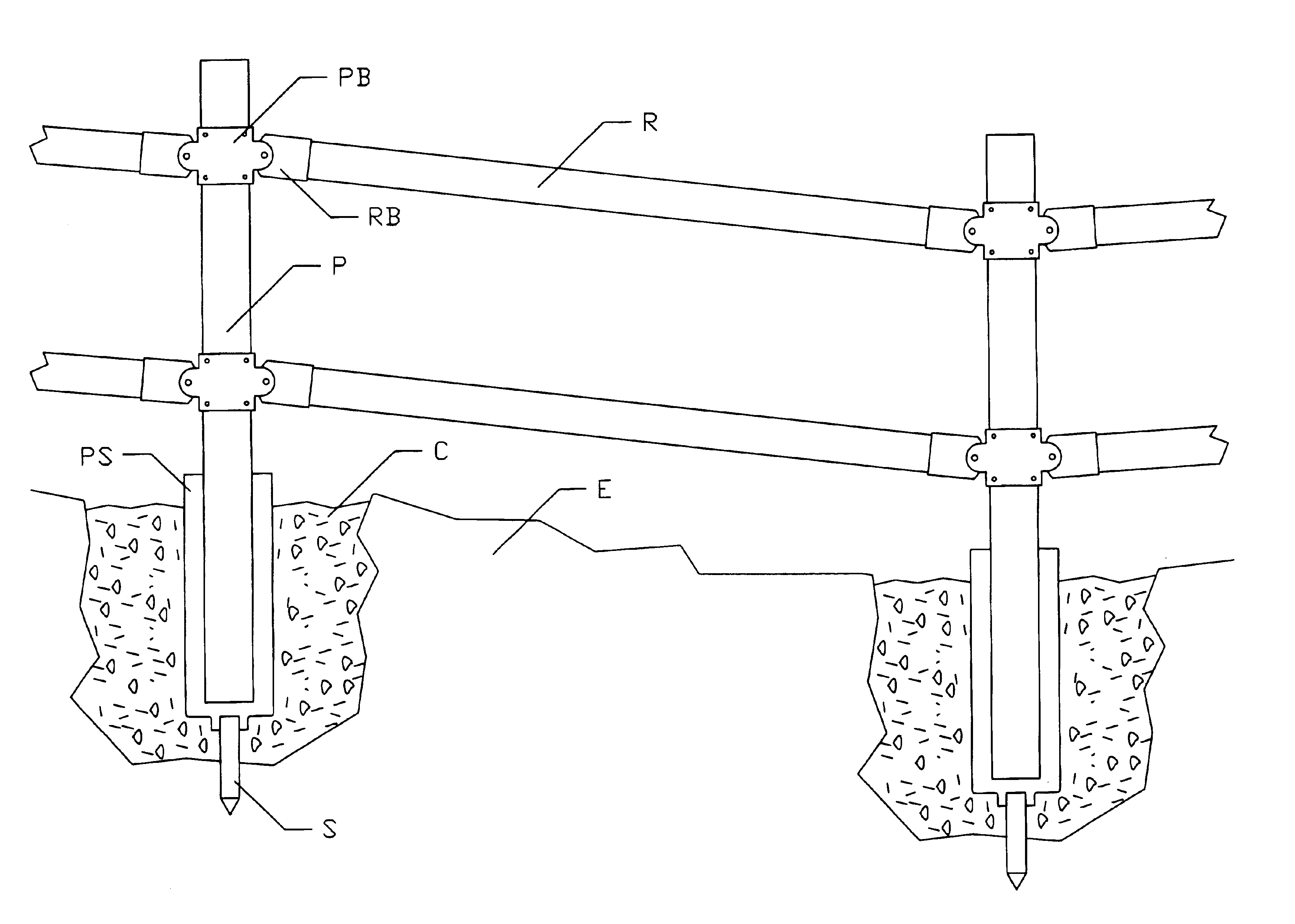
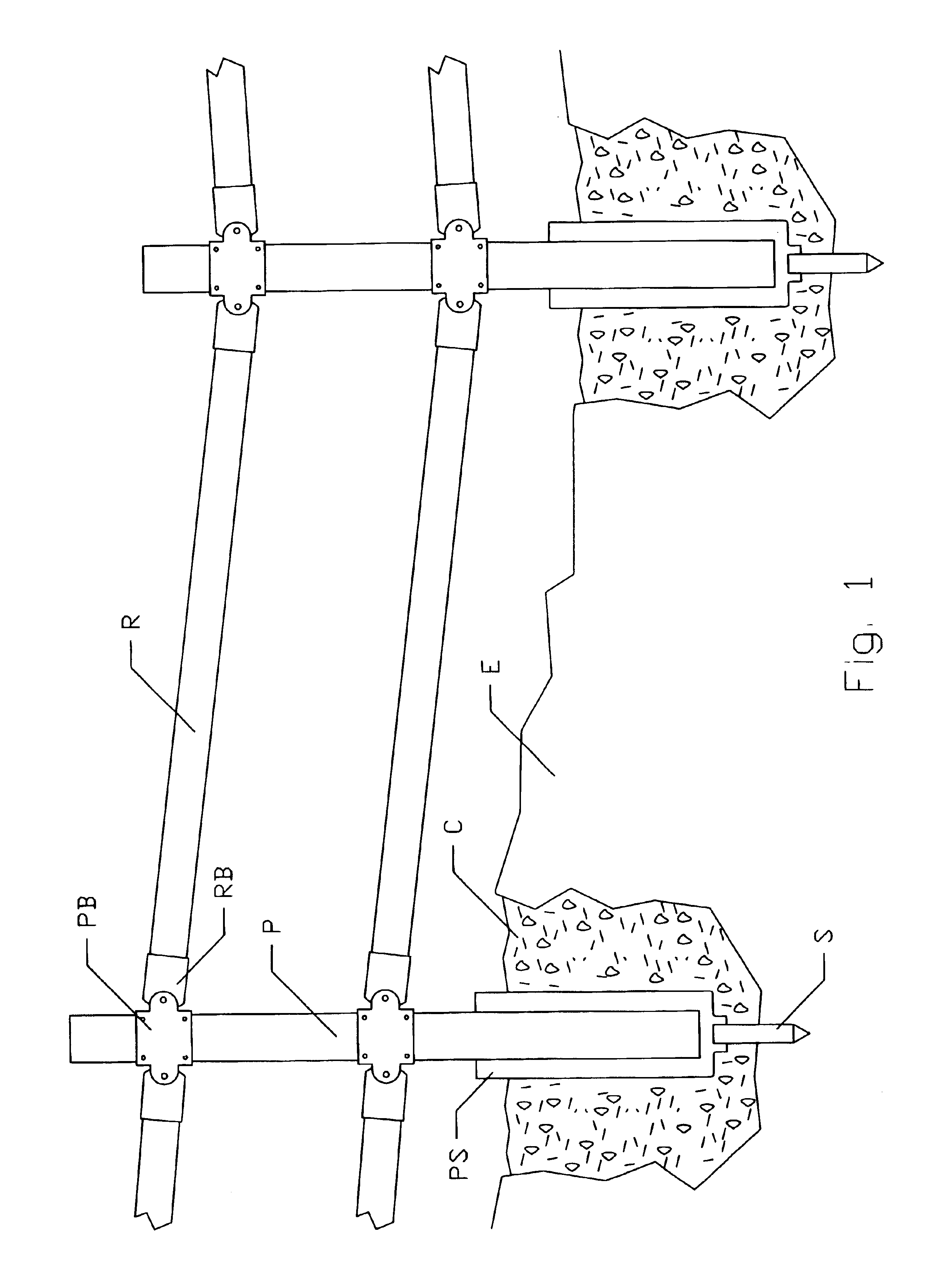
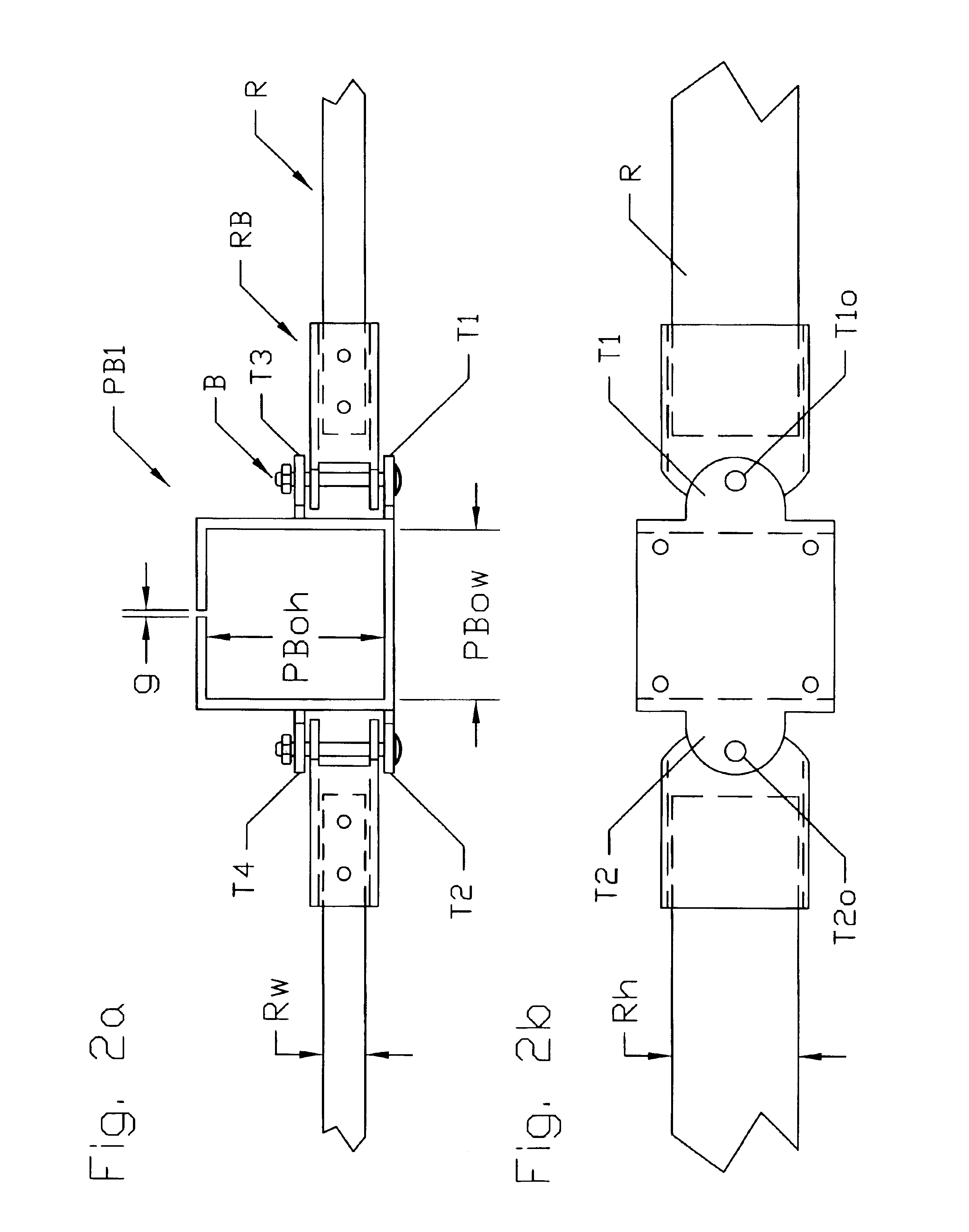
Bracket system for assembling a fence that includes posts and rails, wherein the bracket system includes a post bracket including a first projecting portion and a second projecting portion. The post bracket is securable to a post. The first projecting portion extends in one direction and the second projecting portion extends a different direction. A first rail bracket includes a first end securable to the first projecting portion and a second end that is securable a rail. A second rail bracket includes a first end securable to the second projecting portion and a second end that is securable another rail. The post bracket has an internal opening whose size and shape generally corresponds to a size and shape of the post. Each of the first and second rail brackets is configured to lengthen or shorten a respective rail upon movement of the post bracket relative to the post. Prior to being secured thereto, the post bracket can slide up and down relative to the post.

Description

1. Field of the InventionThe invention relates to a fence bracket system and a fence system which uses the fence bracket system. A method of making the fence bracket system as well as the fence system is also described. The invention is also directed to a method of assembling and / or installing a fence on site using the fence bracket system.2. Discussion of Background InformationVarious types of fence assembly devices are known. It is also known to utilize brackets in attaching fence sections or rails to fence posts. However, none of the numerous conventional bracket systems are able to produce a fence that is very strong, while being easily adjustable and / or repairable, easy and inexpensive to make, and which can be used to efficiently assemble a fence.The invention provides for a bracket system for assembling a fence that includes posts and rails. The bracket system comprises a post bracket including a first projecting portion and a second projecting portion, the post bracket being...

Claims


Application Information

Patent Timeline
Patent Type & Authority Patents(United States)
IPC IPC(8): E04H17/14
CPCE04H17/1413E04H17/1434Y10T16/5345E04H2017/1473E04H2017/1491E04H2017/1452E04H17/143E04H17/1473E04H17/1452E04H17/1448E04H17/1488
Inventor PRETA, JOHN
Owner PRETA JOHN
Learn More