The present invention generally comprises a hubless caster device for use with furniture, equipment, carts, and other conveyances. This
new device provides better stability, better rolling functionality, and many flexible design implementations.
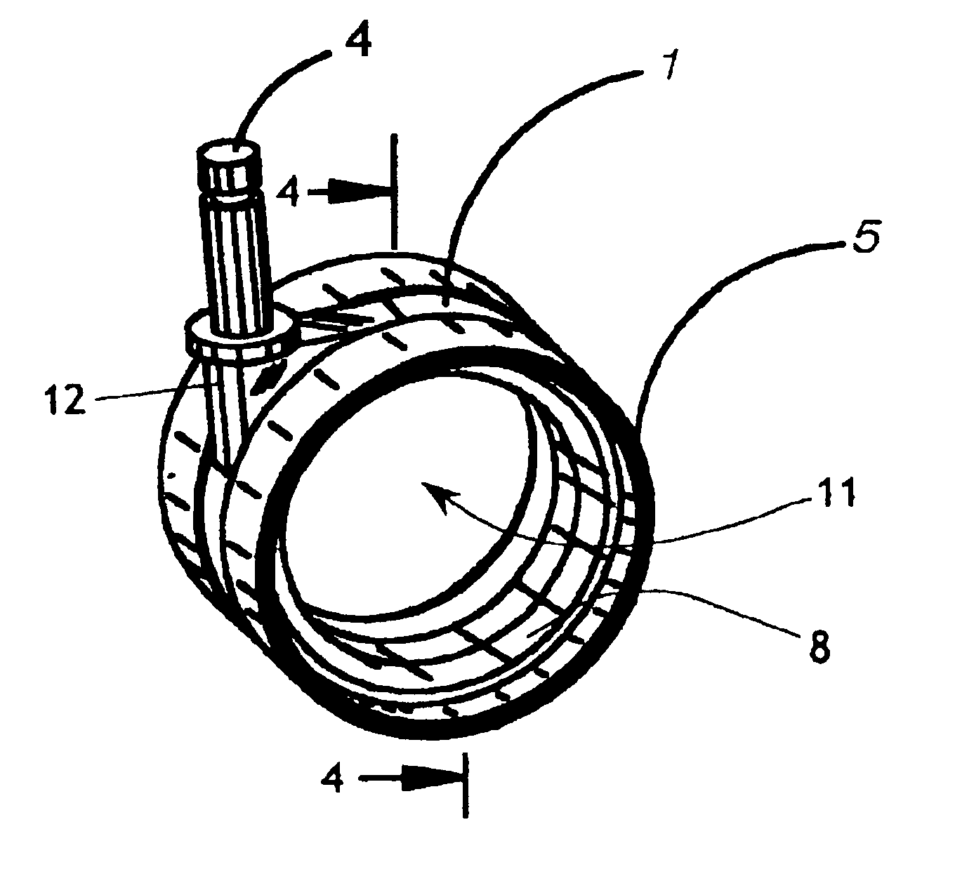
The hubless caster shares some basic features with prior art caster designs: the central base component providing structure and a vertical pin, which attaches the central base component to the chair and allows the caster to pivot about the vertical pin. However, the present invention is unique in a very fundamental way, which provides great advantages over existing art. The device employs two wheels, each located at opposite ends of the base. The wheels are not disc shaped as is most common. Rather, the wheels are annular (doughnut shaped) with no central disk wall or any other structure inside the opening that extends through the annulus. Thus the largest, most visually dominant portion of the typical prior art designs is eliminated, The outside
diameter of the wheel is circular and smooth, for efficient ground-engaging contact. The inside
diameter is provided with a toroidal groove that is adapted to receive roller bearings, either cylindrical or
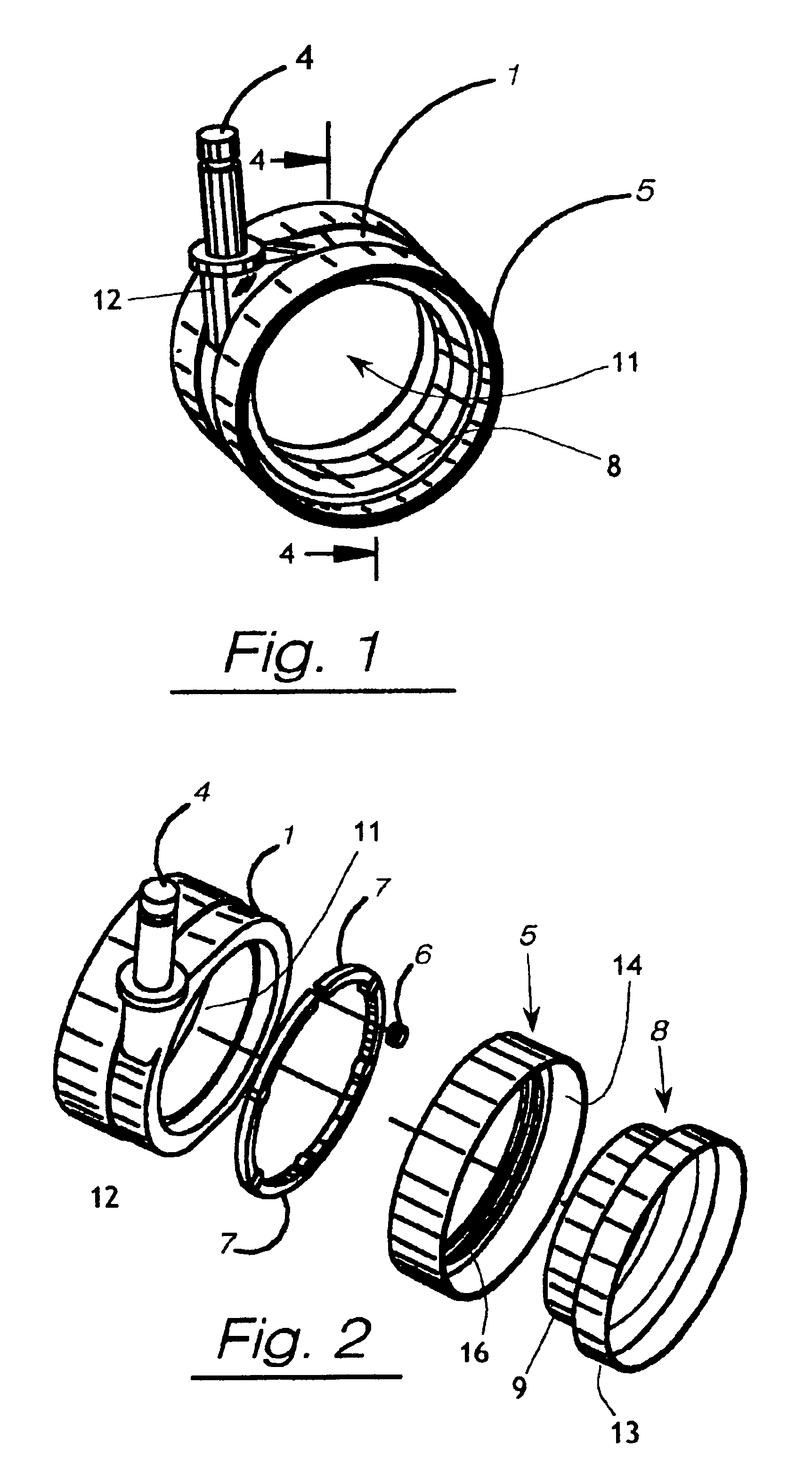
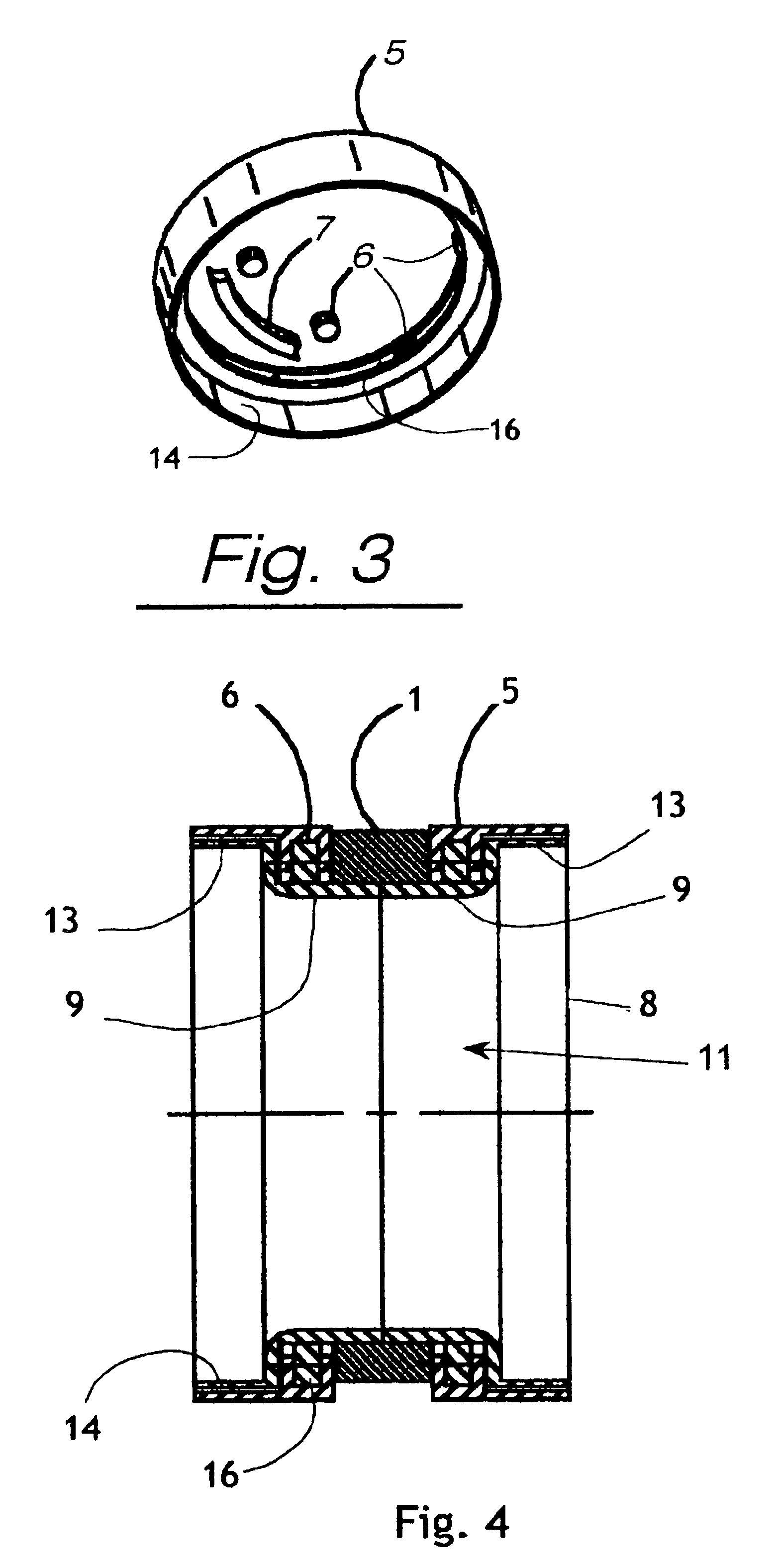
ball type. The central base component includes a ring body, and two arrays of roller bearings are disposed at opposed sides of the ring body, each array engaging the groove of one of the wheels. The bearings support the wheels and permit rolling friction of the wheel about an axis defined by the centering ring portion of the base. The two wheels share a common ring body but do not share a common axle, bearings, nor support groove, so that each wheel is free to rotate independently. By eliminating the common center axle, the need for the center section of the base is obviated. Thus the wheels and the center base are open through-and through, greatly altering the
visual appearance (compared to prior art designs) by permitting light to pass through the center of the caster assembly.
The use of rolling bearings allows better rolling as line friction has been virtually eliminated. Of course, bearings are very commonly used in wheel applications, mostly as ball bearings. However, in this invention the bearing arrangement differs in that the balls ride in grooves that are integral to the wheel and the base. Also, the bearings are not concentrated close to the
axis of symmetry, as in central axle designs in the prior art, but are spaced apart near the outside
diameter of the wheel where the wheel makes contact. This location provides a far more stable wheeled device in that any side loads (moment) are not transmitted via a lever arm (the
radius of the wheel) further out to the center of rotation. The loads are transmitted to the bearings, which occupy a minimum space, thereby reducing the lever arm and providing less play in the
system. Also, the grooves ‘capture’ the bearings very tightly (each ball surrounded by four planes). In this way, the balled joint has very little play and greatly reduces any wobble that occurs when a wheel is simply supported by an axle.
The
elimination of the small diameter central axle enhances stability by virtue of the geometry of the
mechanics of the assembly. Stiffness of a section is enhanced by geometry in which features are far from the center of
neutral axis. (I.e., a
pipe is stiffer than a rod if both are made of same material and employ same amounts of material.) With the wheels (via the bearings and centering ring) riding on the base directly (and not on an axle), the entire base becomes sole support for the wheels, with the enhanced effects of better stiffness and therefore a more stable overall device. Additionally, the base is far stronger than a simple axle and is more resilient to any
impact on the device, hence it has better
longevity.
The
elimination of a central axle and the material that would normally surround it in the base provides the hubless caster with a distinct
advantage over the existing art. This ‘hubless’ feature removes the visual prominence of the wheel and allows the base (in its simplified form) to be more apparent. This leads to greater opportunities to customize the caster by incorporating design elements of the overall design of the end device, such as a chair or furniture item or skateboard. If left open, the hubless caster will allow a skateboard or chair itself to appear to be ‘floating’. If desired, the central hubless area may be used to add features that are consistent and / or distinctive with the entire chair such as holes, cutouts, different colors, imprinted logos,
reflective surfaces, translucent materials, similar materials, fabrics, and so on. The ease of customization will allow an
infinite number of possible customizations to allow the hubless caster to be tailored for visual distinctiveness and design conformance with the overall aesthetic. This feature makes it very distinctive over the ubiquitous black twin wheeled caster.

