Rotor hub for wind turbine, and associated rotor arrangement and wind turbine

A technology for rotor hubs and facilities, which is applied to wind turbines in the same direction as the wind, the assembly of wind turbines, the configuration of installing/supporting wind turbines, etc., which can solve problems such as adverse effects, increase material costs, and increase the quality of hubs, and achieve The effect of reducing ring stress

Pending Publication Date: 2022-05-13
WOBBEN PROPERTIES GMBH
View PDF6 Cites 0 Cited by
  • Summary
  • Abstract
  • Description
  • Claims
  • Application Information

AI Technical Summary

Problems solved by technology

[0007] Although the described solution prevents fatigue cracks in the drilled holes of the outer ring of the bearing in a satisfactory manner and method, this construction increases the mass of the hub
The increased mass involved generally makes installation of the hub difficult, increases material costs and can adversely affect the moment of inertia

Method used


Image

  • Rotor hub for wind turbine, and associated rotor arrangement and wind turbine
  • Rotor hub for wind turbine, and associated rotor arrangement and wind turbine
  • Rotor hub for wind turbine, and associated rotor arrangement and wind turbine

Examples


Embodiment Construction

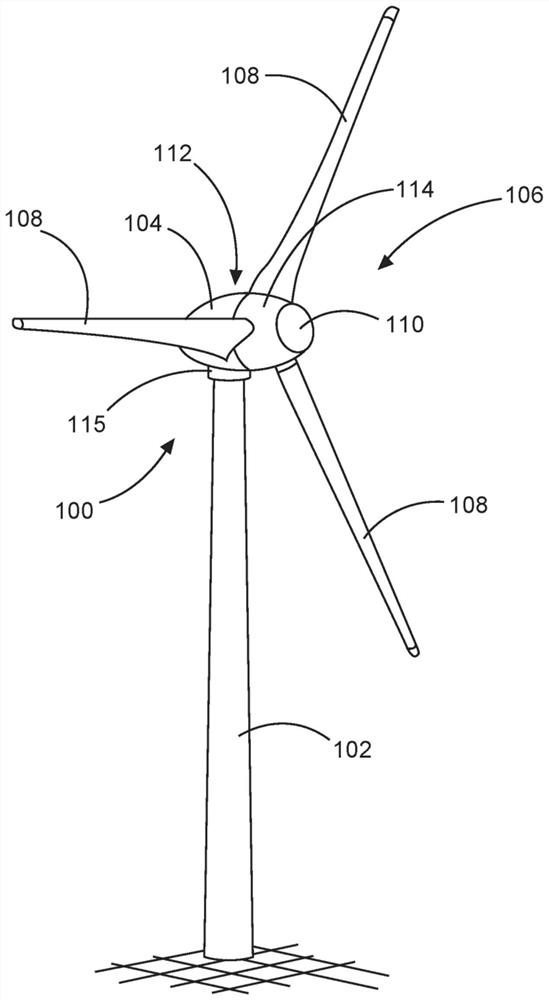
[0035] figure 1 A wind energy installation 100 is shown with a tower 102 on which a pod 104 is mounted by means of a pivot connection 115 . A generator 112 (shown only schematically in the figure) is accommodated in the gondola 104 . The rotor arrangement 106 for driving the generator 112 is connected in a rotationally fixed manner to the generator 112 . The rotor arrangement 106 has a rotor hub 114 and rotor blades 108 . The pitch angle of the rotor blades 108 is adjustable, and the rotor blades are each by means of a blade bearing 146 (see Figure 5 and Figure 6 , not shown here) is accommodated on the rotor hub 114 . The spinner 110 is arranged on the rotor hub 114 on the side facing away from the generator 112 . The rotor arrangement 106 drives a generator 112 to generate electrical current.

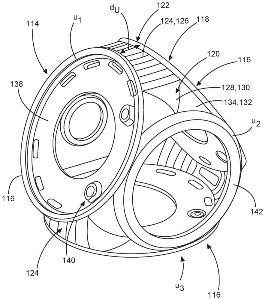
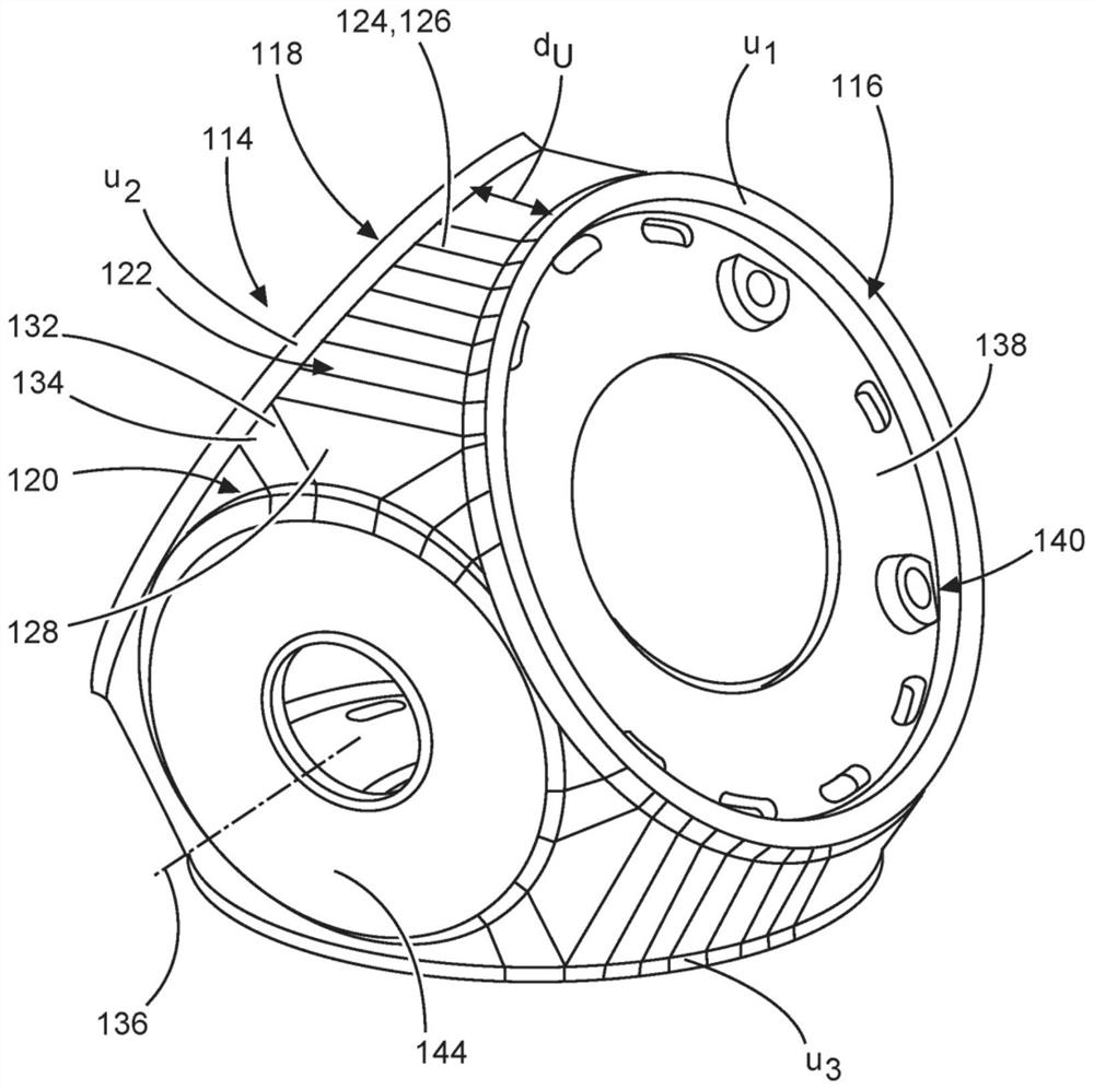
[0036] exist Figures 2 to 5 A rotor hub 114 according to the invention is shown in and firstly referred to figure 2 to describe. The rotor hub 114 has a housing 118 with ...


PUM


Abstract

The invention relates to a rotor hub (114) for a wind turbine (100), comprising at least two flange sections (116) for each receiving a rotor blade (108), the rotor hub (114) having a housing (118) with a wall (120) which is interrupted by the flange sections (116), the housing (118) having a wall region (122) between two adjacent flange sections (116). The invention further relates to a rotor arrangement (106) for a wind turbine (100) and to a wind turbine (100). According to the invention, a face section (124) having a cylindrical curvature (126) is formed in the wall region (122).

Description

technical field [0001] The invention relates to a rotor hub for a wind energy installation, which has at least two flange sections for respectively receiving a rotor blade, wherein the rotor hub has a housing with a wall, which Interrupted by flange sections, the housing having a wall region between two adjacent flange sections. Background technique [0002] In the German application based on priority, the German Patent and Trademark Office searched the following documents: US7 614 850B2, US 2013 / 0202448 A1, US 2015 / 0337796 A1, EP 3 492 734B1, EP 2 947 316A1, EP 3 453871A1. [0003] Rotor hubs of the type mentioned at the outset are known, for example, from wind energy installations. A related wind energy installation has a tower, a nacelle, a generator and a rotor hub connected to the generator. The rotor hub is connected to a plurality of rotor blades, wherein the rotor blades are each arranged on a flange section of the rotor hub by means of a blade bearing. [0004] S...

Claims


Application Information

Patent Timeline
Patent Type & Authority Applications(China)
IPC IPC(8): F03D1/06F03D13/10F03D13/20
CPCF03D1/0633F03D1/0675F03D13/20F03D13/10F05B2250/231F03D1/0691F03D1/0608Y02E10/72F05B2260/30F16B2200/50
Inventor 约尔格·许勒尔弗洛里安·萨托里乌斯维尔科·古德韦尔
Owner WOBBEN PROPERTIES GMBH
Why Eureka
Try Eureka