Method and apparatus for stimulating heavy oil production

a technology of heavy oil and apparatus, applied in the field of resource extraction, can solve the problems of difficult extraction of oil from typically tightly packed sand formations, heat loss, and release of greenhouse gases such as carbon dioxide, and achieve the effects of increasing interfacial contact area, rapid extraction of bitumen, and promoting solvent penetration

Inactive Publication Date: 2005-04-26
HATCH LTD
View PDF34 Cites 104 Cited by
  • Summary
  • Abstract
  • Description
  • Claims
  • Application Information

AI Technical Summary

Benefits of technology

[0012]This invention is directed to identifying what mixture of vapours is present in the reservoir, determining the effect such a mixture may have on any condensing solvent heat transfer into the bitumen or heavy oil and implementing process steps and conditions to counter any negative effects. In particular this invention considers the effect of less condensable impurities in the solvent on the heat and mass transfer rates. This invention comprehends establishing process conditions and materials to reduce a vulnerability to heat transfer and / or mass transfer “poisoning” caused by less condensable compounds. Thus, the present invention provides solutions for managing the same whether such compounds are naturally present in the formation, are released during the extraction process into the extraction chamber or are co-injected as impurities with a feed solvent.
[0013]The present invention comprehends establishing process conditions for the recovery process for ensuring that heat generated in the thermal process is delivered to the extraction chamber surface in conditions permitting recovery to be optimized. The present invention has greatest effect for heavy oils, but is also applicable to enhancing recovery of less viscous oils.
[0014]In one aspect the present invention is directed to a means to produce heavy oil and bitumen at moderate temperatures with simultaneous in situ upgrading. The present invention is directed to a condensing solvent recovery process which has much lower energy requirements relative to steam assisted gravity drainage (SAGD) and simultaneously upgrades the heavy oil in situ. Such a recovery process decreases the cost of extraction while simultaneously increasing the value of the production thereby improving both the operating and profit margins. In addition, such a process provides a more energy efficient extraction technique that reduces the greenhouse gas emissions by more than ⅔ compared to existing SAGD commercial technology.
[0015]The present invention is also directed to a recovery process that economically accelerates oil production rate by encouraging the rapid extraction of bitumen. The preferred process accelerates the extraction rate through injection of heated solvent vapour into the recovery chamber formed in the reservoir. As the solvent condenses on a cold bitumen extraction surface it supplies heat and dilution to the bitumen interface to accelerate the extraction. In the most preferred form of the present invention no water or steam is co-injected, avoiding the problems associated with the presence of a liquid water phase in the formation.
[0023]Another object is to provide a process that operates at elevated temperature and pressure to mitigate the effect of naturally occurring heat and mass transfer poisons in the heavy oil or bitumen reservoir.
[0025]Another object is to provide a process and apparatus for a solvent vapour extraction process that operates at pressures just below, at, or just above the reservoir fracture pressure, to promote solvent penetration into the bitumen, increase the interfacial contact area and provide rapid extraction of the bitumen.

Problems solved by technology

These characteristics make it difficult to extract the oil from the typically tightly packed sand formations found in tar sands, because, unlike lighter oil deposits, heavy oil and bitumen do not readily flow.
Steam extraction is subject to a number of problems, including heat losses during injection, clay swelling problems, thief zones, water-oil emulsions, capillary surface tension effects and lack of confinement for shallower zones, and therefore is not widely used.
Thermal recovery processes using steam also require using large amounts of energy to produce the steam in the first place, which releases enormous amounts of greenhouse gases such as carbon dioxide.
With the high cost of natural gas, many operators will use less expensive coal, coke or bitumen.
However, such fuels generate about twice as much carbon dioxide emissions per bbl of steam as natural gas.
However to date there has not been a successful commercial pilot of this cold solvent approach.
The predicted production rates from laboratory tests are simply too slow to yield a cost effective treatment.
Bench tests2 using solvent (propane) and sand have shown that production rates can be increased about 20 fold simply by increasing the extraction temperature from 20C to 90° C. However, Butler2 indicated that propane was unsuitable for direct heating and proposed indirect heating of the propane vapour by co-injection of hot water.
However, co-injection of steam or hot water which is heated above grade also suffers from a number of problems, such as countercurrent heat exchange problems during startup, formation damage problems with clays, and non-Newtonian emulsions, capillary pressure issues, water treatment, water supply, and reduced oil permeability due to high water saturations.
Steam has such a low volumetric heat capacity that is unsuitable at lower extraction temperatures.
Ethane has such a low critical temperature that it is unable to deliver latent heat above about 30C.
Although various forms of condensing heat transfer such as SAGD, and the Suncor reflux system have been proposed, the effect of light gases which are difficult to condense in an extraction or solvent chamber process have neither been understood nor accounted for.
This may be because such light gases are typically lost before samples are placed in laboratory tests, meaning that testing results are obtained from “dead” samples.

Method used


Image

  • Method and apparatus for stimulating heavy oil production
  • Method and apparatus for stimulating heavy oil production
  • Method and apparatus for stimulating heavy oil production

Examples


Embodiment Construction

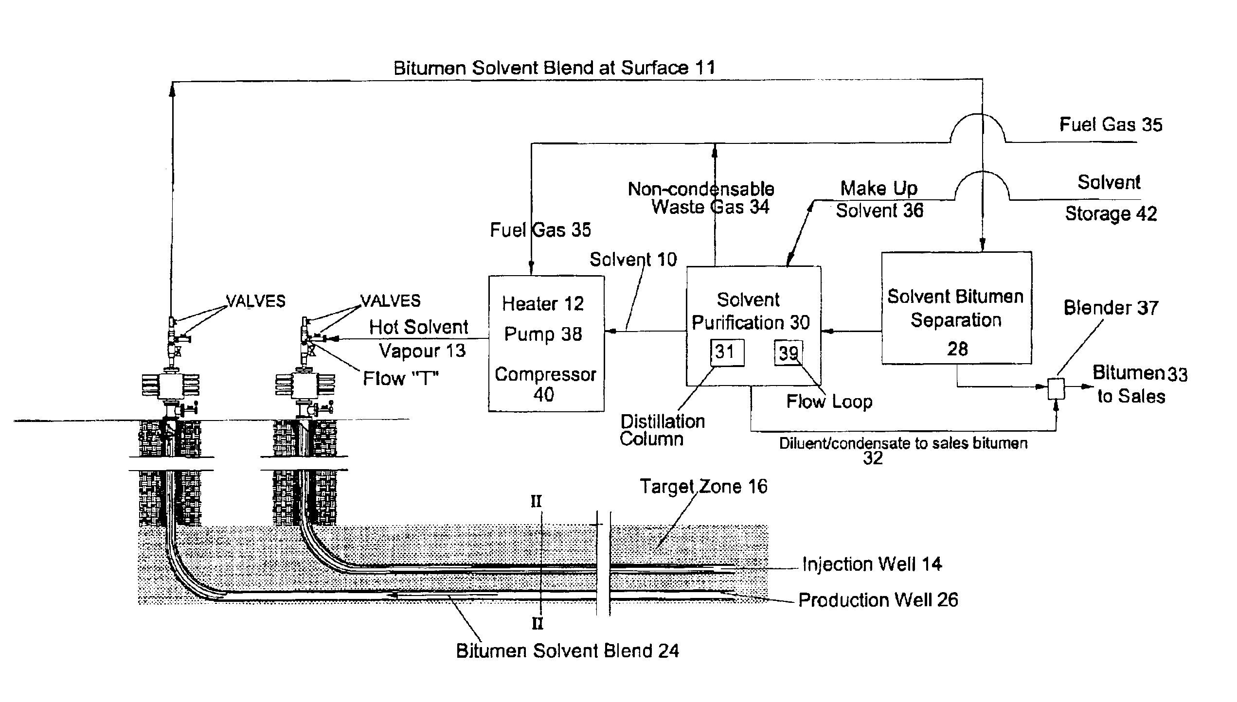
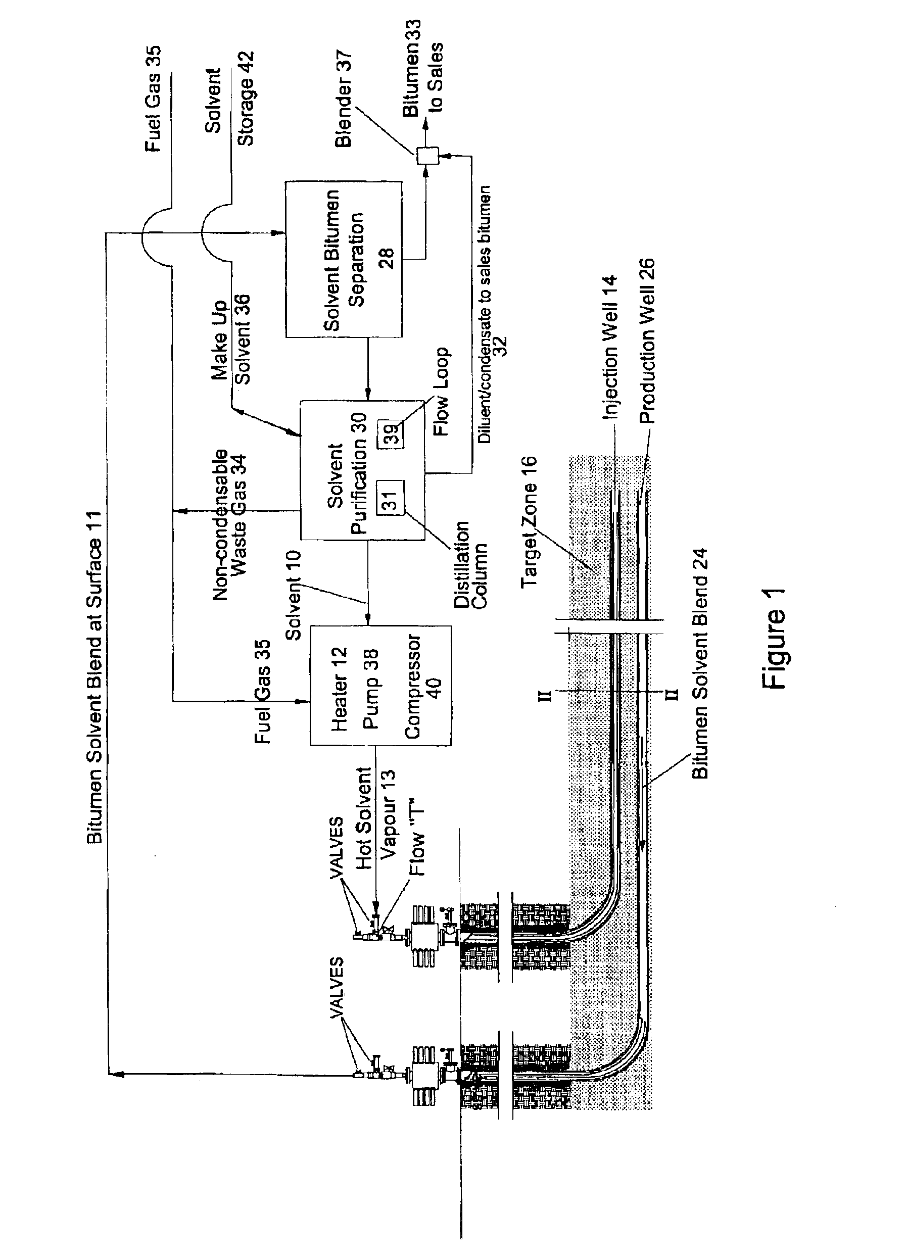
[0036]FIG. 1 shows the general elements for a recovery process according to the present invention. In some respects the elements are similar to that shown in earlier patent application 2,299,790. However, as is explained in more detail below, the recovery process of the present invention includes several key improvements.

[0037]FIG. 1 shows a solvent 10 being heated above grade 11 in a heater 12. The hot solvent 13 is injected down the injection well 14 into the recovery reservoir 16. In this specification the term “solvent” means a compound which dissolves into and thus, reduces the viscosity of, naturally occurring hydrocarbons in the recovery formation. The preferred solvent is capable of being heated to a vapour state at recovery pressure so as to condense at a recovery face in the formation. A preferred solvent is a C3 to C5 hydrocarbon such as propane, propylene, butane, pentane or the like. The most preferred solvent is propane. The present invention comprehends that the solve...


PUM

PropertyMeasurementUnit
temperatureaaaaaaaaaa
distancesaaaaaaaaaa
pressureaaaaaaaaaa

Abstract

A process for the recovery of hydrocarbons from a hydrocarbon bearing formation having an extraction chamber where the extraction chamber has an extraction surface. The process has the steps of heating a solvent, such as propane, and then placing the solvent into the extraction chamber at a temperature and a pressure sufficient for the solvent to be in a vapor state in the chamber and to condense on the extraction surface. The next step is to produce a liquid blend of solvent and heavy oil and then to separate the solvent from said heavy oil. Then the solvent is purified, before being re-injected into the formation again. The purification step removes less condensable fractions from the solvent to ensure a purity that is high enough to support continued heat transfer at extraction conditions. The pressure and temperature are set to levels to cause less condensable fractions to drain away with the liquid bitumen and solvent blend that is produced, thus mitigating heat transfer poisoning.

Description

FIELD OF THE INVENTION[0001]This patent applies generally to the field of resource extraction and more particularly to the recovery of hydrocarbons for use as fuel. Most particularly this invention relates to the recovery of heavy oils and bitumen from, for example, tar sand deposits.BACKGROUND OF THE INVENTION[0002]Tar sands, such as are found in Alberta, Canada, contain vast reserves of hydrocarbon resources, of the type referred to as heavy oil and bitumen. Heavy oil means crude oil that has high specific gravity and viscosity. These characteristics make it difficult to extract the oil from the typically tightly packed sand formations found in tar sands, because, unlike lighter oil deposits, heavy oil and bitumen do not readily flow.[0003]In the past steam has been injected into the oil-bearing formation to improve the rate of bitumen and heavy oil extraction. There are a number of different stream extraction techniques, including steam cycling, steam floods and more recently ste...

Claims


Application Information

Patent Timeline
Patent Type & Authority Patents(United States)
IPC IPC(8): C10G1/00C10G1/04E21B43/34E21B43/16
CPCC10G1/04E21B43/34E21B43/168Y02P30/00
Inventor NENNIGER, JOHNNENNIGER, EMIL
Owner HATCH LTD
Why Eureka
Try Eureka