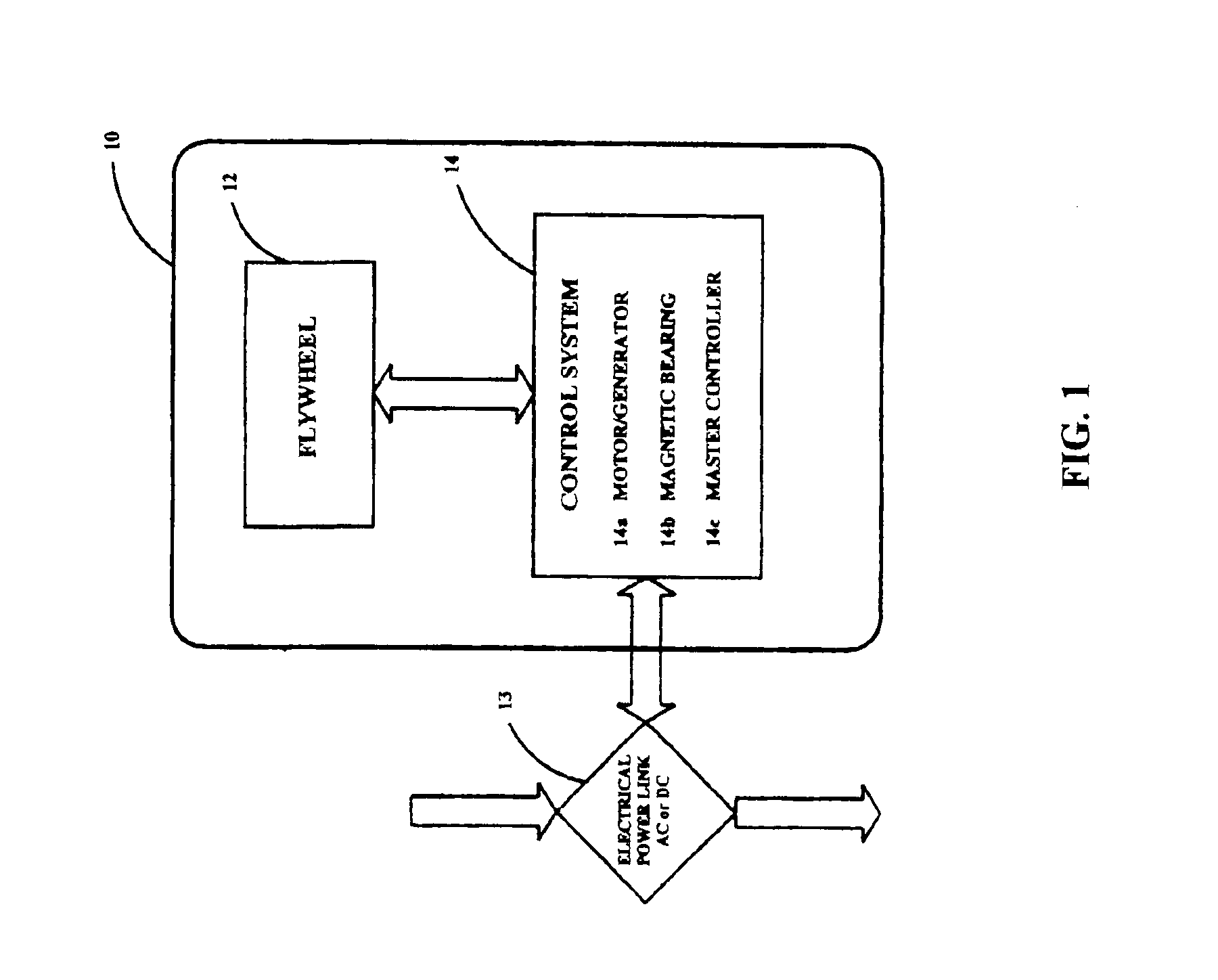
[0006]The present invention provides an optimized
flywheel energy storage system utilizing magnetic bearings, a high speed
permanent magnet motor / generator, and a high strength flywheel system. The flywheel system is preferably constructed using a
high strength steel wheel for
kinetic energy storage, high efficiency magnetic bearings configured as a
dual thrust and radial acting permanent
magnet combination active magnetic bearings, and a high efficiency permanent
magnet motor generator. The steel wheel provides a cost effective, high speed construction for the energy storage rotor in contradistinction to a
composite material which, while enhancing the energy storage density in the system, increases system cost.
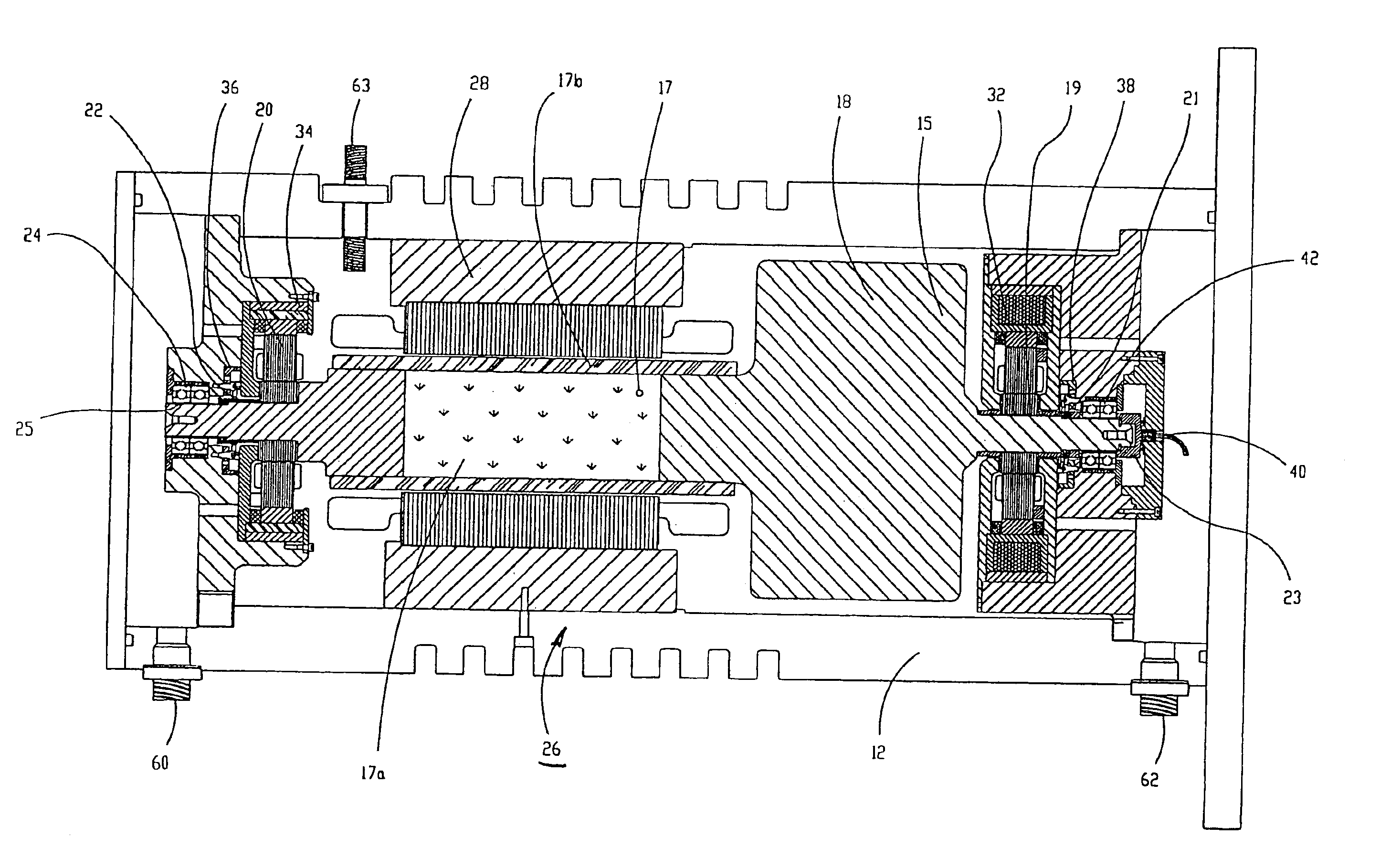
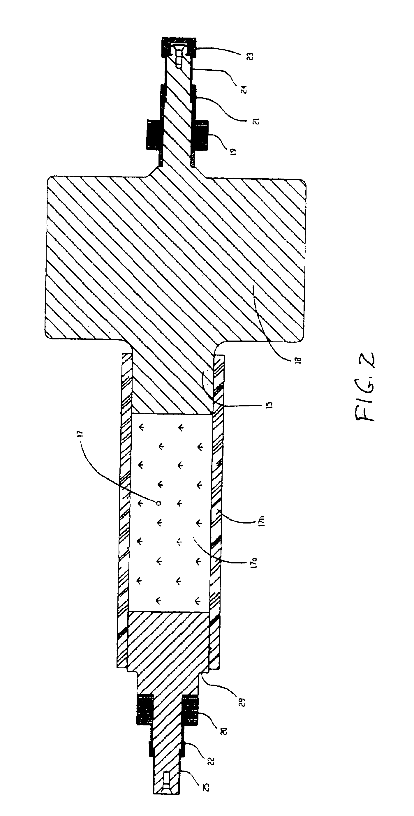
[0007]Two permanent magnet combination magnetic bearings are used, the first combination
magnetic bearing being configured as a conventional, fully active three axis
magnetic bearing with a permanent magnet bias as set forth in copending application Ser. No. 10 / 078,572, filed Feb. 20, 2002, now U.S. Pat. No. 6,727,617 and issued Apr. 27, 2004 and assigned to the assignee of the present invention. This homopolar configuration minimizes rotor losses due to
magnetic field variations to keep rotor heating minimized. This heat minimization is critical for the flywheel, since with no physical contact between rotor and
stator, radiating heat from the rotor to
stator is the only way to provide for rotor cooling. The homopolar combination bearing provides active
radial position control for two radial axes on one end of the shaft (X1, Y1) and also provides active
axial load to
pickup and maintain the axial position of the rotor. Configured in a
vertical orientation to gravity, this configuration minimizes radial loads and input power requirements.
[0009]Magnetic bearings are critical for long term, low maintenance operation in that they offer minimum rotor losses, have long life and do not require
lubrication. The size of these bearings depends on the weight of the rotor for the axial axis, and the allowable system tilt during installation for the radial axes. While ball bearings combined with an active axial magnetic bearing minimizes
axial load on the ball bearings, even mounting tilts of 1-2 degrees can
cut operating life in half by adding load to the bearings. Magnetic bearings are not limited in life due to load. They can operate within a maximum load range with no affect on life, giving them a significant
advantage in ground installations when ground shifting could cause system tilt to be in the range between 5-10 degrees, thereby increasing lifetimes of the ground installation. This system can use ball bearings for radial support for low life systems that necessitate minimum upfront cost.
[0010]The PM motor / generator also is an important component for this type of system. The motor / generator is located between the two bearings (not in an overhung manner) thus providing a robust rotor dynamic system and allows for ease of scaling to a larger power system. With rotor losses being critical for a successful system, these must be minimum for the motor / generator. The permanent magnet configuration in either the two or more pole rotors, depending on
operating speed, is well suited for high speed operation and minimum rotor losses, as well as high efficiency. High efficiency is critical in the standby mode of such an energy storage device to hold
power over a long duration.
Power electronics interface with the motor / generator for adding energy to the flywheel and for providing an output to
discharge energy from the flywheel. The
electronics monitor the power
bus and flywheel speed and switch between input and output accordingly. They can be configured for either a DC or AC
bus for most applications including battery replacement.
[0011]The forces provided by permanent magnets require no power source, reducing connectors and current drivers while increasing reliability. In addition, utilizing a steel flywheel minimizes cost while still achieving
high power density in the wheel. Although the
power density is less than that provided by a
composite material, it is well balanced to meet commercial performance requirements at acceptable costs, characteristics which cannot be met by systems using composite technologies.
[0012]A steel flywheel section provides the necessary
mass for
effective energy storage.
High strength steel (such as ANSI 4340) is used to allow for high operating hub surface speeds. These
high surface speeds reduce the
mass of the wheel required, and with the low loss magnetic bearings and
motor generator, high speeds are readily achievable for a very compact energy storage system. The complete rotating group is mechanically coupled via the hub, motor / generator rotor and bearing
support system for a
high stiffness rotor construction. The stationary bearings and motor / generator assemblies are mechanically linked and aligned via a housing and bolted together. The housing utilizes seals to effectively hold a vacuum to eliminate
windage losses on the rotating members and sealed electrical connectors allow for bearing sensor signals and input power to the flywheel. A separate set of sealed connectors are used for motor / generator input and output power for
electrical energy storage and
discharge for the system. Connectors can be minimized by integrating bearing
electronics into the flywheel housing, thus only requiring input power and outputting data signals.

