
Valve plug seal assembly

a valve plug and seal assembly technology, applied in the direction of engine components, mechanical equipment, transportation and packaging, etc., can solve the problems of high wear, high hardness of materials, and the need for routine replacement of seals

Inactive Publication Date: 2005-01-11
FISHER CONTROLS INT LLC
View PDF27 Cites 33 Cited by
  • Summary
  • Abstract
  • Description
  • Claims
  • Application Information

AI Technical Summary

Problems solved by technology

While the flexibility of materials such as TEFLON® improves the quality of the seal, such materials typically have a low hardness and therefore are susceptible to damage from foreign material in the vicinity of the seal.
As a result, the seal is a high-wear component that requires routine replacement.
As a result, such frequent seal replacement interrupts service, and is overly costly and time-consuming.
The spring-loaded seal having a TEFLON® jacket is useable in processes having a temperature of up to 450 degrees F. When the process temperature is above 450 degrees F., a risk arises that the seal may be extruded through the gap between the plug and cage.

Method used


Image

  • Valve plug seal assembly
  • Valve plug seal assembly
  • Valve plug seal assembly

Examples


Embodiment Construction

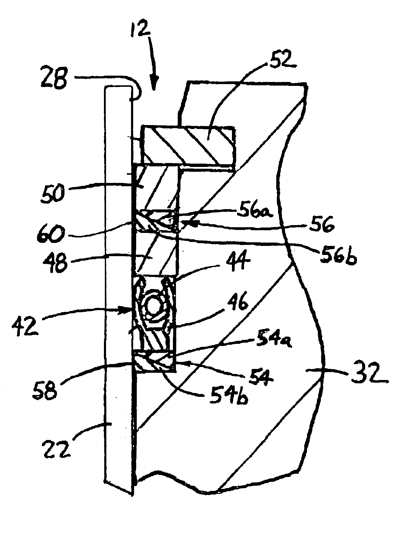
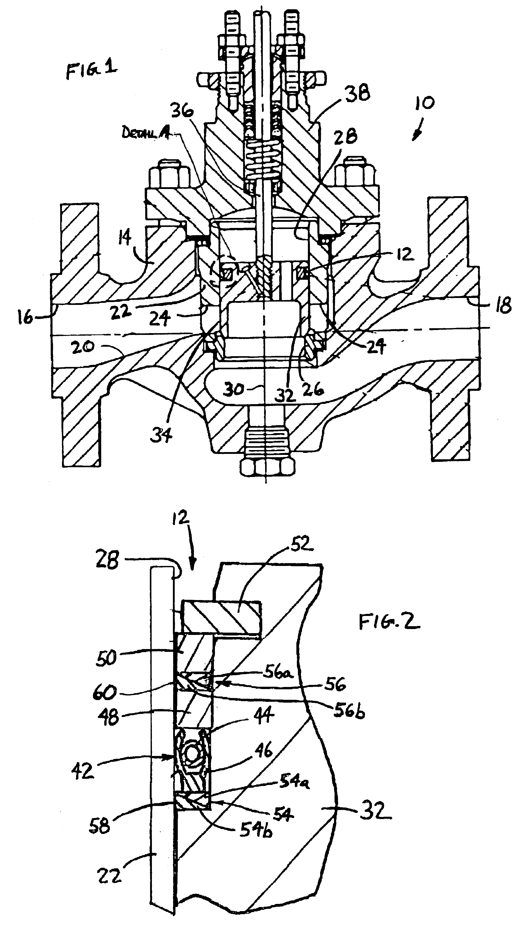
FIG. 1 illustrates a valve 10 including a seal assembly 12 in accordance with the teachings of the present invention. The valve 10 includes a body 14 defining an inlet 16 and an outlet 18. The inlet 16 and outlet 18 shown in FIG. 1 assume a fluid flow from left to right through the valve 10. It will be appreciated, however, that the fluid flow may be in the reverse direction (i.e., from right to left) and therefore the inlet and outlet positions may be switched without departing from the teachings of the present invention. The valve body 14 further defines a fluid flow path 20 extending from the inlet 16 to the outlet 18.

A cage 22 is positioned in the fluid flow path 20 to influence desired characteristics of the fluid flow. The cage 22 has orifices 24 formed therein to allow fluid to flow through the cage from the inlet 16 to the outlet 18. The orifices 24 may be formed to alleviate detrimental fluid flow characteristics. For example, the orifices 24 may enhance pressure reduction ...


PUM


Abstract

A seal assembly is adapted for use in a valve having a trim cage with an inner surface extending along an axis and a plug sized to fit inside the trim cage inner surface, wherein the plug is adapted to move along the axis. The seal assembly includes a spring-loaded seal ring disposed between the plug and the trim cage inner surface, the seal ring including a center spring member and a jacket formed of a fluoropolymer resin to tightly seal between the plug and the trim cage inner surface. A first wiper ring is disposed between the plug and the trim cage inner surface and positioned axially upstream of the seal ring, and a second wiper ring is disposed between the plug and the trim cage inner surface and positioned axially downstream of the seal ring. Each of the first and second wiper rings has an outside surface sized to engage the trim cage inner surface and is formed of a material sufficiently rigid to scrape foreign material from the bore surface yet sufficiently soft to minimize damage to the bore.

Description

FIELD OF THE INVENTIONThe present invention generally relates to seal assemblies and, more particularly, to seals used with valve plugs.BACKGROUND OF THE INVENTIONValves are commonly used to control the flow characteristics of a fluid. A conventional valve includes a valve body defining an inlet, an outlet, and a fluid flow path extending between the inlet and the outlet. A throttling element, such as a plug, is disposed in the path to control fluid flow. A stem connects the valve plug to an actuator, which moves the valve plug into and out of the flow path. A conventional valve may include a cage extending across the fluid flow path and having orifices formed therein. The plug has an outer surface sized to closely fit an inner wall of the cage. As a result, the plug is slidable inside the cage between a closed position, in which the plug obstructs the orifices, and an open position, in which the plug is clear of at least a portion of the orifices.A seal is typically provided betwee...

Claims


Application Information

Patent Timeline
Patent Type & Authority Patents(United States)
IPC IPC(8): F16K3/24F16K47/00F16K3/00F16K47/08
CPCF16K47/08F16K3/243F16J15/00Y10T137/86799
Inventor FAAS, WAYNE R.GRABAU, TED D.BARRON, KIMBALL R.
Owner FISHER CONTROLS INT LLC
Features
  • Generate Ideas
  • Intellectual Property
  • Life Sciences
  • Materials
  • Tech Scout
  • Unparalleled Data Quality
  • Higher Quality Content
  • 60% Fewer Hallucinations
Learn More