Reclosable packaging having zipper with sculpted slider end stops
a technology of end stops and sliding stops, which is applied in the direction of flexible container closures, snap fasteners, buckles, etc., can solve the problems of ineffective end stops and the tendency of the vertical end to fold
- Summary
- Abstract
- Description
- Claims
- Application Information
AI Technical Summary
Problems solved by technology
Method used
Image

Examples
first embodiment
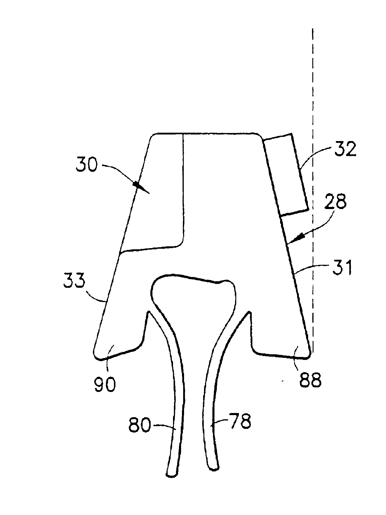
the invention is depicted in FIGS. 5 and 6. The interlocked zipper parts of zipper 12 are stomped along an end section by application of ultrasound wave energy. Preferably, an ultrasonic horn and anvil are used to sculpt the end section to form the geometric end shape shown in FIGS. 5 and 6, the horn having a projection for forming a recess on one side of the zipper and the anvil having a pocket for forming a projection on the other side of the zipper. It should be appreciated that prior to stomping, the zipper parts in the end section are interlocked but not joined. After stomping, the zipper parts in the end section are ultrasonically welded together. Thus, the respective zipper parts 2 and 4 cannot be distinguished when the zipper is viewed from the end, as seen in FIG. 5. The welded end section is designated 28 in FIGS. 5 and 6. In addition, the thermoplastic zipper material in the welded end section is sculpted to have a recess 30 on one side of a midplane of the zipper and a p...
second embodiment
the invention is depicted in FIGS. 7 and 8. Again, the interlocked zipper parts of the zipper are stomped along an end section by application of ultrasound wave energy. As in the first embodiment, the second embodiment comprises a recess 30 formed on one side of the zipper midplane. However, instead of the end stop being formed by a projection or nub on the side surface on the other side of the zipper midplane, the slider end stop 34 projects upward. This is accomplished by providing an anvil that has an inclined flat surface that contacts the side surface of the A-shaped zipper and directs flowing thermoplastic zipper material along that inclined flat surface. The slider end stop 34 projects to an elevation higher than an elevation of a top surface of the intermediate interlockable section of the zipper, is laterally offset relative to a vertical midplane of the intermediate section of the zipper (in other words, a major portion of the slider end stop lies on one side of the zipper...
third embodiment
the invention is depicted in FIGS. 9 and 10. Again, the interlocked zipper parts of the zipper are stomped along an end section by application of ultrasound wave energy. As in the earlier disclosed embodiments, the third embodiment comprises a recess 30 formed on one side of the vertical midplane of the zipper. However, in this third embodiment, the slider end stop projects both upward and laterally outward. In particular, the slider end stop comprises a portion 34 that projects upward to an elevation higher than an elevation of a top surface of the interlockable intermediate section of the zipper and a portion 32′ that projects laterally beyond a side surface 31 of the intermediate section of the zipper. It will be appreciated by a person skilled in the art that these portions 32′ and 34 are integrally formed with each other (and with adjoining portions of the welded end section) and that, in fact, a portion of the upwelled thermoplastic material that projects both outward and late...
PUM
| Property | Measurement | Unit |
|---|---|---|
| flexible | aaaaa | aaaaa |
| elevation | aaaaa | aaaaa |
| ultrasonic energy | aaaaa | aaaaa |
Abstract
Description
Claims
Application Information
PatSnap Eureka turns technology decisions into work you can execute. Powered by our Innovation Knowledge Graph, it runs expert workflows across engineering, life sciences, materials and intellectual property. Get your review-ready output in minutes.


