Vertical take-off and landing aircraft

a vertical take-off and landing technology, applied in the field of aircraft, can solve the problems of reducing the lift of the aircraft, affecting so as to improve the stability of the hover

Active Publication Date: 2005-01-18
MORGAN AIRCRAFT LLC
View PDF6 Cites 167 Cited by
  • Summary
  • Abstract
  • Description
  • Claims
  • Application Information

AI Technical Summary

Benefits of technology

Finally, it is another object of the present invention to provide a VTOL aircraft, which has improved hover stability over that of a helicopter.

Problems solved by technology

A drawback to this design is that there is an inherent “danger zone” of time, while the lift of the aircraft is reduced as its wings / propellers are rotated into the forward flight position.
The same danger of losing lift is present with the redirected thrust.

Method used


Image

  • Vertical take-off and landing aircraft
  • Vertical take-off and landing aircraft
  • Vertical take-off and landing aircraft

Examples


Embodiment Construction

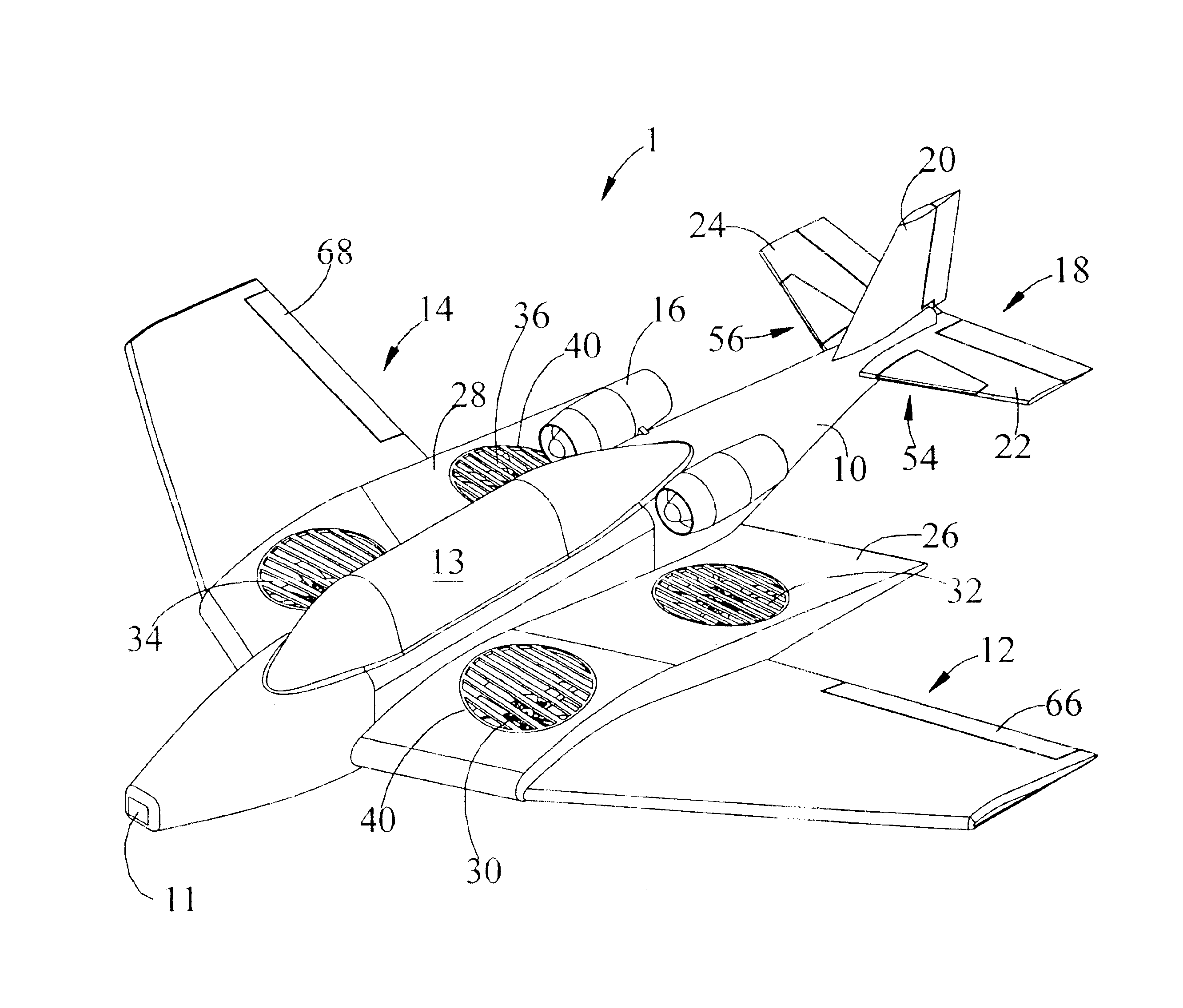
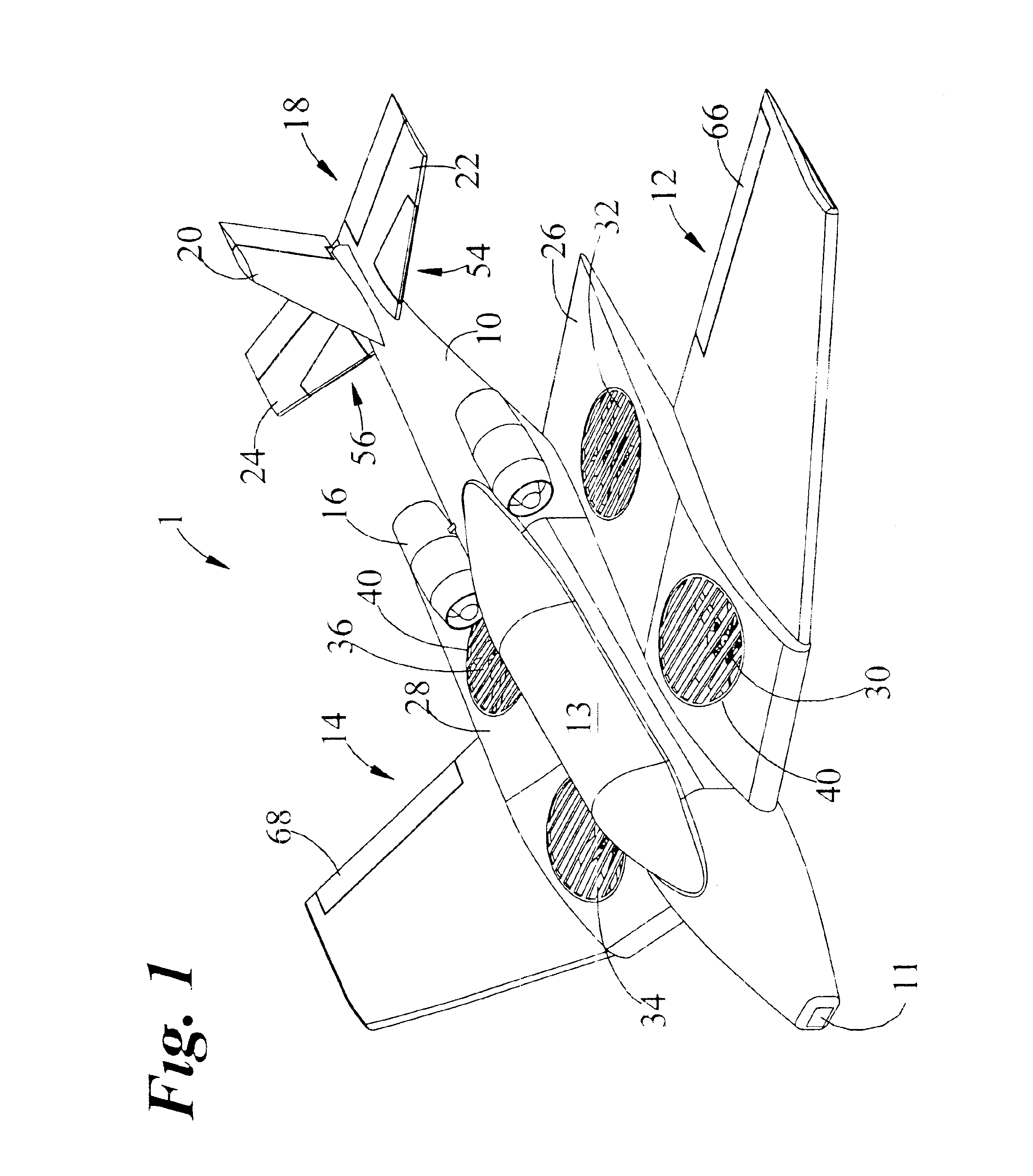
With reference now to the drawings, and particularly to FIG. 1, there is shown a perspective view of a VTOL aircraft 1. The VTOL aircraft 1 includes a fuselage 10, a left wing 12, a right wing 14, at least one forward thruster 16, a horizontal stabilizer 18 and a vertical stabilizer 20. The left wing 12 extends from a left side of the fuselage 10 at substantially a middle thereof and the right wing 14 extends from a right side of the fuselage 10 at substantially a middle thereof. The at least one forward thruster 16 is preferably mounted to the fuselage 10, substantially behind the left and right wings. The horizontal stabilizer 18 includes a left horizontal stabilizer portion 22 and a right horizontal stabilizer portion 24. The left horizontal stabilizer portion 22 extends from a left side of the fuselage 10 at a rear thereof and the right horizontal stabilizer portion 24 extends from a right side of the fuselage 10 at a rear thereof. The vertical stabilizer 20 extends from a top o...


PUM


Abstract

A vertical take-off and landing aircraft includes a fuselage, a left wing, a right wing, at least one forward thruster, a horizontal stabilizer and a vertical stabilizer. The left and right wings extend from substantially a middle of the fuselage on left and right sides, respectively. The at least one forward thruster is preferably mounted to the fuselage, substantially behind the left and right wings. The horizontal stabilizer extends from a rear of the fuselage. The vertical stabilizer extends from a top of the fuselage at a rear thereof. At least two left lift rotors are retained in the left wing and at least two right lift rotors are retained in the right wing. A second embodiment of the VTOL aircraft includes a fuselage truncated behind the left and right wings with a twin tail empennage.

Description

BACKGROUND OF THE INVENTION1. Field of the InventionThe present invention relates generally to aircraft and more specifically to a vertical take-off and landing aircraft, which includes improved stability in hover flight over that of a helicopter.2. Discussion of the Prior ArtThe prior art provides several different types of vertical take-off and landing (VTOL) aircraft. One common VTOL method is that of a tilt-rotor design, where typically two larger propellers are mounted to the ends of an abbreviated wing that is designed to tilt the rotors from a vertical position to a horizontal position for normal flight. A drawback to this design is that there is an inherent “danger zone” of time, while the lift of the aircraft is reduced as its wings / propellers are rotated into the forward flight position. One example of the above challenge is encountered by the U.S. military's “Osprey” aircraft.Another common VTOL method is known as redirected thrust. Although technically the same in terms ...

Claims


Application Information

Patent Timeline
Patent Type & Authority Patents(United States)
IPC IPC(8): B64C5/02B64C29/00B64C5/00
CPCB64C29/0025B64C5/02
Inventor MORGAN, BRIAN H.
Owner MORGAN AIRCRAFT LLC
Why Eureka
Try Eureka