
Occupant restraint system

a technology for occupants and seats, applied in the direction of pedestrian/occupant safety arrangements, vehicular safety arrangments, vehicle components, etc., can solve the problems of preventing smooth deployment, insufficient inflated parts, and insufficient impact absorption effect of parts

Inactive Publication Date: 2005-01-18
HONDA MOTOR CO LTD
View PDF15 Cites 30 Cited by
  • Summary
  • Abstract
  • Description
  • Claims
  • Application Information

AI Technical Summary

Benefits of technology

A second object of the present invention is to smoothly deploy an airbag that has a plurality of cells and is folded along fold lines.
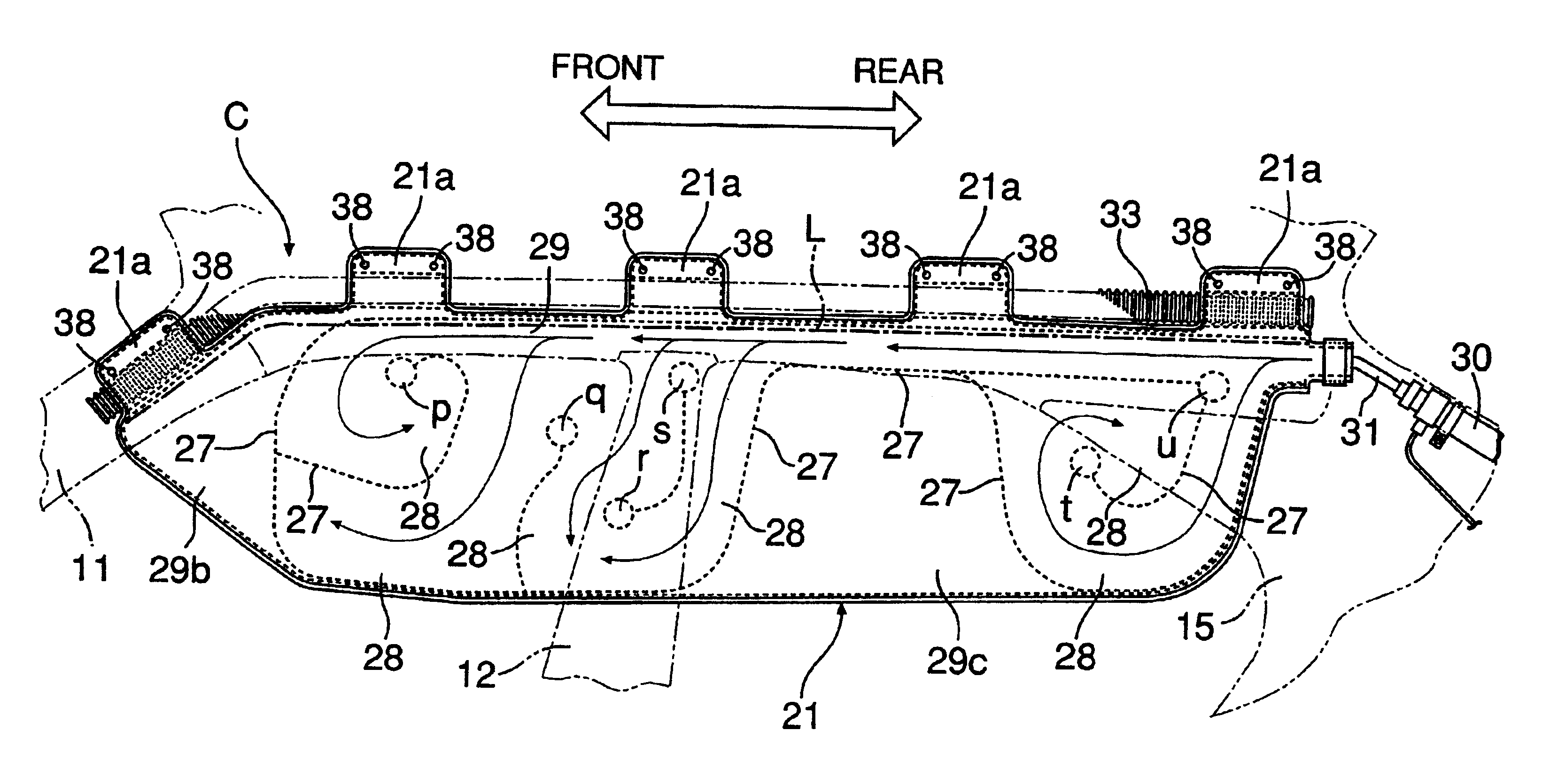
In accordance with this arrangement, since the end parts of the cells that are inflated by the gas generated by the inflator are not vertically aligned relative to the fold line of the airbag extending in the longitudinal direction of the vehicle, the timing of the gas flowing into the end parts of the plurality of cells is staggered, thus preventing the individual cells from bending in two at the center in the vertical direction, and thereby smoothly deploying the airbag.

Problems solved by technology

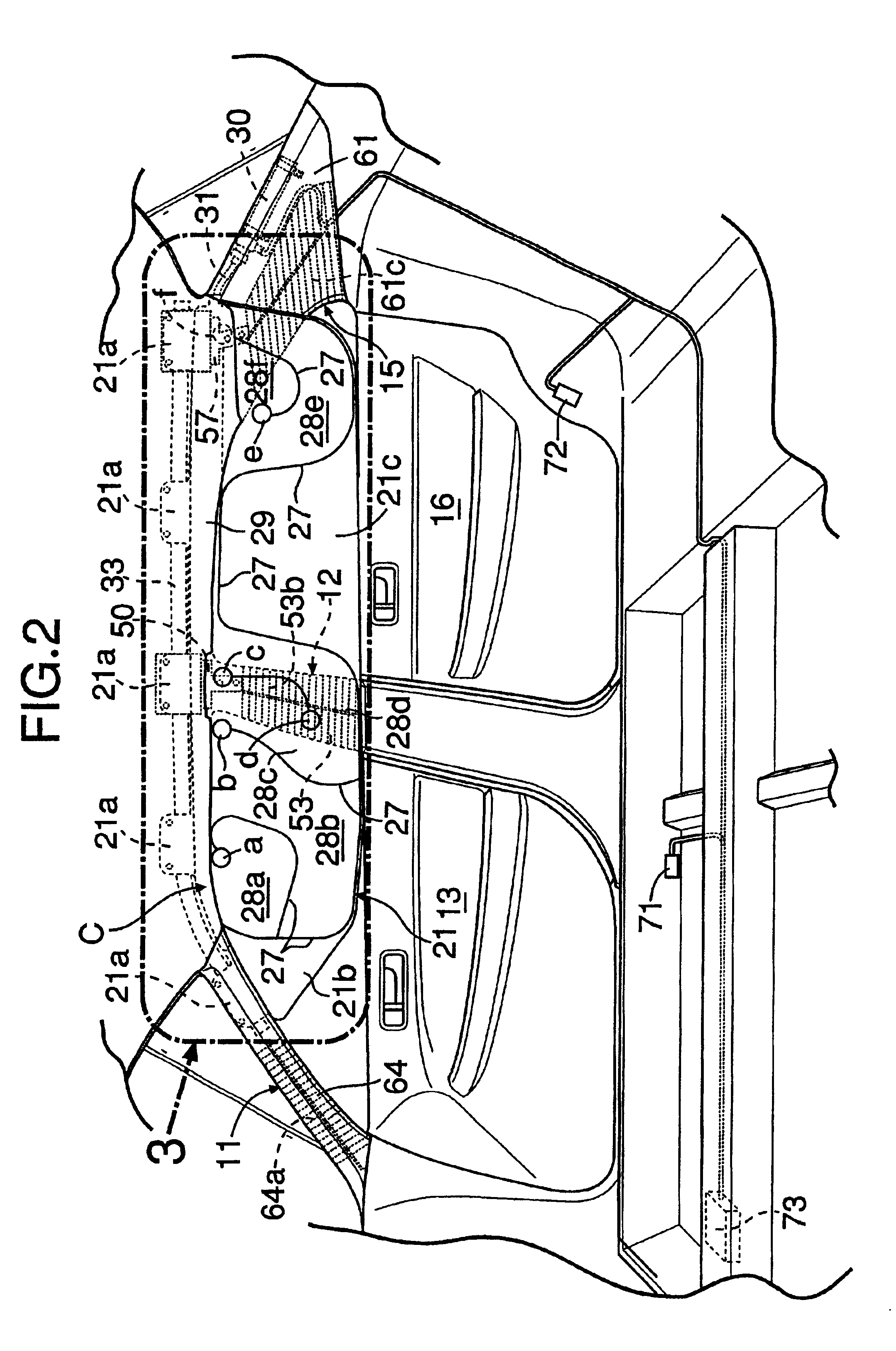
As a result, the cell end parts, formed by the point where the stitching stops, cannot be inflated sufficiently since the two sheets of fabric are united by sewing, and there is a possibility that these parts might have an insufficient impact-absorbing effect.
Furthermore, if the upper ends of the cells extending to the upper communicating passage of the airbag are aligned along one of the fold lines, in some cases the pressure of the gas inflating the airbag might be distributed equally to all of the cells, resulting in individual cells becoming bent in two at the center in the vertical direction, and preventing smooth deployment.

Method used


Image

  • Occupant restraint system
  • Occupant restraint system
  • Occupant restraint system

Examples


first embodiment

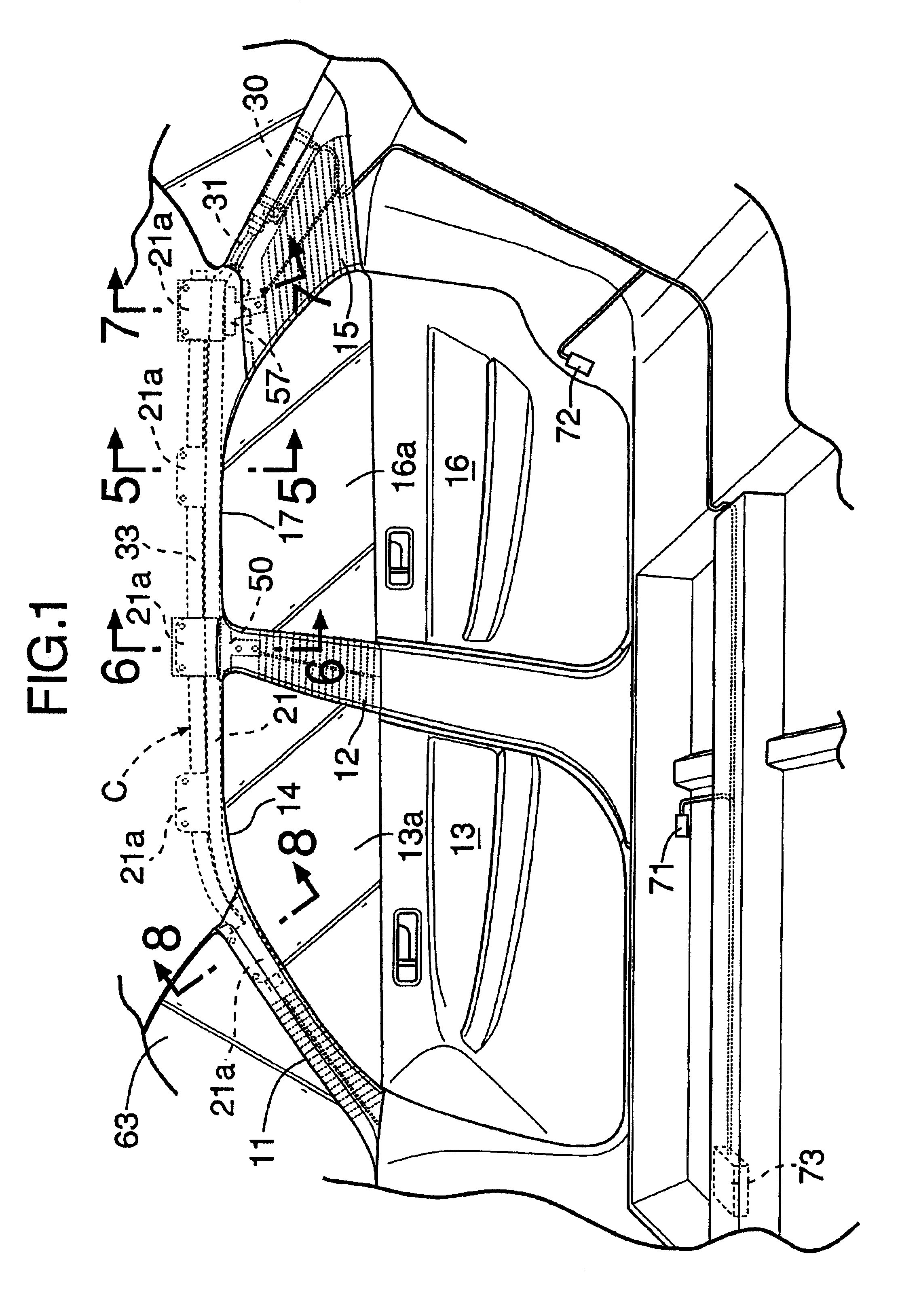
the present invention is explained by reference to FIGS. 1 to 12.

Referring to FIG. 1, formed between a front pillar 11 and a center pillar 12 on a vehicle body side face is a door opening 14 in which a front door 13 is mounted, and formed between the center pillar 12 and a rear pillar 15 is a door opening 17 in which a rear door 16 is mounted. A roof side rail 18 (see FIG. 5) extends in the longitudinal direction of the vehicle body, so as to provide a connection between the upper end of the front pillar 11 and the upper end of the rear pillar 15. The roof side rail 18 defines the upper edges of the door openings 14 and 17 of the front door 13 and the rear door 16. An occupant restraint system C is provided along the roof side rail 18. The occupant restraint system C is provided on each of the left and right sides of the vehicle body. The occupant restraint systems on the respective left and right sides have a substantially identical mirror-image structure, and that provided on the ...


PUM


Abstract

An occupant restraint system includes a side airbag and an inflator. The airbag includes six cells that are defined by stitching and are adapted to be inflated by a gas generated by the inflator. Among six end parts a to f of these cells, four end parts b to e are positioned on top of or in the vicinity of a center pillar garnish and a rear pillar garnish that include respective impact absorbing ribs. When the airbag is deployed, even if the end parts b to e cannot be inflated sufficiently due to the stitching, thereby exhibiting no impact-absorbing effect, the center pillar garnish and the rear pillar garnish instead exhibit an impact-absorbing effect, thereby protecting an occupant.

Description

BACKGROUND OF THE INVENTION1. Field of the InventionThe present invention relates to an occupant restraint system in which a side airbag is disposed in a folded state along an upper edge of a door opening of a vehicle body, and the airbag is inflatable by a gas, generated by an inflator, when the vehicle is involved in a collision. Upon activation thereof, the airbag is deployed in a curtain shape along the inner face of a side of an occupant compartment.2. Description of the Related ArtSuch an occupant restraint system is known in, for example, Japanese Patent Application Laid-open Nos. 2000-33847 and 11-235965. The airbag of this type of occupant restraint system is folded in a zigzag manner along fold lines extending in the longitudinal direction and designed so that it deploys when a gas is supplied to a plurality of cells extending downward from an upper communicating passage extending to an inflator.The cells of the airbag are defined by sewing two fabrics superimposed one on ...

Claims


Application Information

Patent Timeline
Patent Type & Authority Patents(United States)
IPC IPC(8): B60R21/16B60R21/04B60R21/20B60R21/213B60R21/215B60R21/232B60R21/233
CPCB60R21/04B60R21/213B60R21/232B60R21/215B60R2021/23316B60R2021/0414B60R2021/0435B60R2021/161
Inventor AOKI, TAKASHIUTSUMI, HIDETOSHIOCHIAI, FUMIHARUSAITA, NAOHIKOSAITO, YUICHI
Owner HONDA MOTOR CO LTD
Learn More