Floor stop for a mobile base

Active Publication Date: 2005-01-18
AFFINITY TOOL WORKS
View PDF25 Cites 47 Cited by
  • Summary
  • Abstract
  • Description
  • Claims
  • Application Information

AI Technical Summary

Problems solved by technology

One of the problems encountered in developing a mobile frame is anchoring the mobile frame once...

Method used


Image

  • Floor stop for a mobile base
  • Floor stop for a mobile base
  • Floor stop for a mobile base

Examples


Embodiment Construction

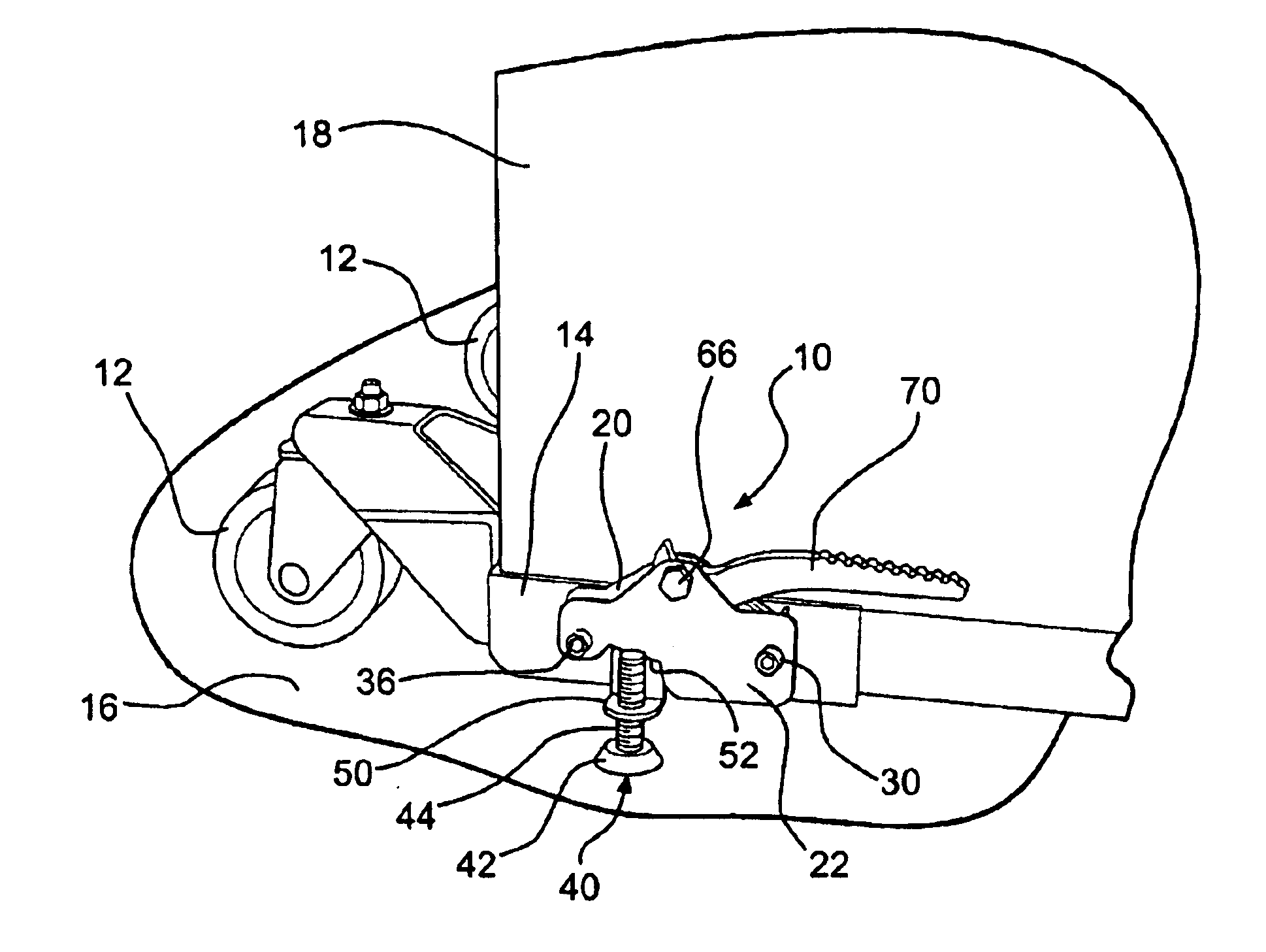
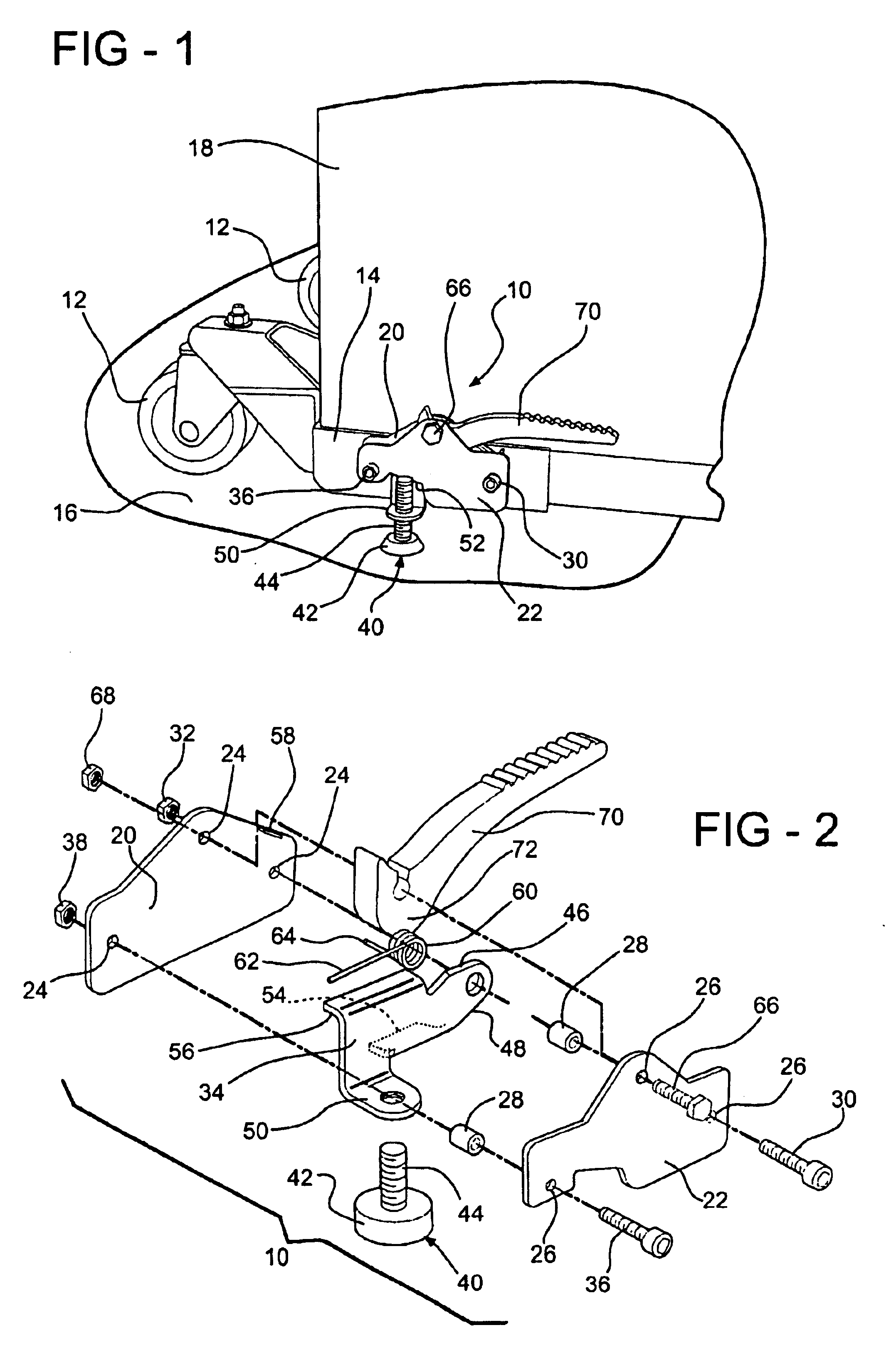
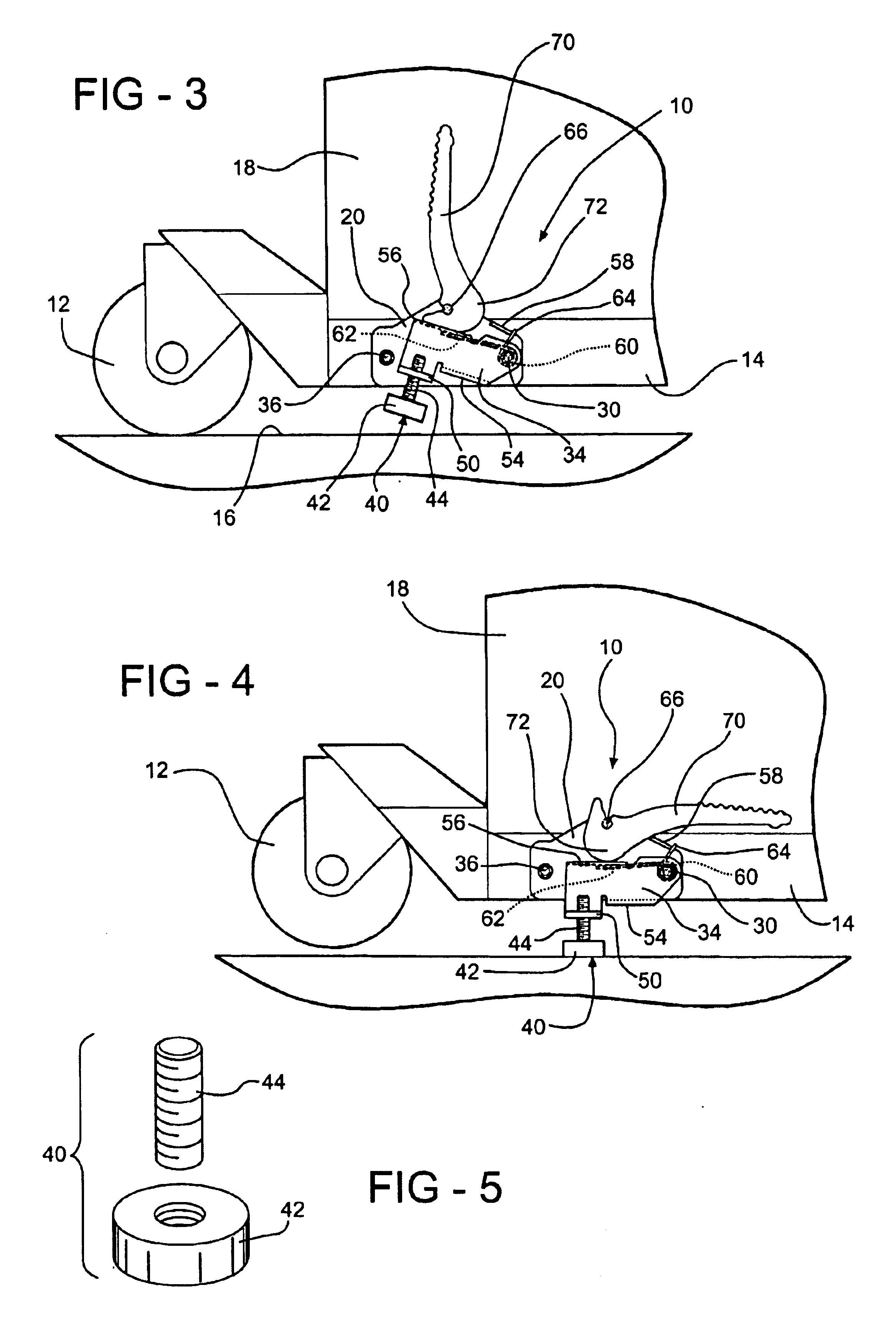
Referring to the Figures, wherein like numerals indicate like parts throughout the several views, an anchor mechanism is generally shown at 10 for lifting the wheels 12 supporting a frame 14 of a mobile base assembly from a support surface 16 and anchoring the frame 14 to the support surface 16. A plurality of wheels 12 is attached to the frame 14 for movably supporting the frame 14 on the support surface 16. The mobile base assembly supports equipment 18 for movement over the support surface 16, such a floor.

The anchor mechanism 10 includes inner 20 and outer 22 plates attached to the frame 14. The inner plate 20 contains a first set of spacer holes 24 and the outer plate 22 contains a second set of spacer holes 26 for alignment with the first set of spacer holes 24 of the inner plate 20. A plurality of cylindrical spacers 28 are disposed between the plates 20, 22 in alignment with the respective spacer holes 24, 26 for spacing the plates 20, 22 in spaced parallel relationship to o...


PUM


Abstract

A mobile base assembly wherein a plurality of wheels 12 are attached to a frame 14 for movably supporting the frame 14 on a support surface 16 and an anchor mechanism 10 lifts the wheels 12 from the support surface 16 and anchors the frame 14 to the support surface 16. A pair of spaced plates (20 or 22) are attached to the frame 14 and an anchor member 34 is pivotally mounted between the plates (20 or 22) for pivotal movement between an anchor position (FIG. 4) and a retracted position (FIG. 3). A lever 70 is pivotally mounted between the plates (20 or 22) and presents a cam 72 for engaging and pivoting the anchor member 34 against the biasing reaction of a spring 60 from the retracted position to the anchor position. A foot 40 is attached to a foot flange extending from the anchor member 34 and has a base 42 for engaging the support surface 16 in the anchor position.

Description

BACKGROUND OF THE INVENTION1. Field of the InventionThe invention relates to mobile base assembly having wheels for supporting equipment for movement over a support surface and, more specifically, to an anchor mechanism for lifting the wheels from the support surface and anchoring the assembly to the support surface.2. Description of the Related ArtMobile base frames are well known to those skilled in the art for transporting heavy or awkward equipment. A typical mobile frame comprises a frame having wheels or some form of rolling mechanism attached to the frame to facilitate movement. The equipment is secured to the frame and is easily moved between locations because of the wheels attached to the frame. One of the problems encountered in developing a mobile frame is anchoring the mobile frame once the mobile frame is moved to a new location.Prior art mechanisms have been developed to serve the purpose of anchoring mobile base frames. Brakes have been developed, such as are commonly...

Claims


Application Information

Patent Timeline
IPC IPC(8): B60P7/08B60P7/06B62B5/04
CPCB60P7/08B62B5/049
Inventor HEWITT, TIMOTHY
Owner AFFINITY TOOL WORKS
Why Eureka
Try Eureka