Electrical termination module

a technology of electrical termination module and termination module, which is applied in the direction of electrical apparatus, substation/switching arrangement details, coupling device connection, etc., can solve the problems of increasing communication lines, increasing problems, and significant effort involved in the relocation or addition of floor boxes, so as to facilitate installation and permit field modification

Inactive Publication Date: 2005-01-18
THOMAS & BETTS INT INC
View PDF27 Cites 43 Cited by
  • Summary
  • Abstract
  • Description
  • Claims
  • Application Information

AI Technical Summary

Benefits of technology

It is an advantage of the present invention to provide an electrical termination module for use in a floor.
It is a further advantage of the present invention to provide an electrical termination module having a modular design to permit field modification and ease of installation.
It is still a further advantage of the present invention to provide an electrical termination floor module having a modular design for accommodating power and data connectors.
In the efficient attainment of these and other advantages, the present invention provides an electrical termination module including side wall. A base plate is removably connected to a lower end of the side wall and a cover flange is supported on an upper end of the side wall. A cover is mounted to the cover flange and movable between an open and closed position. The base plate is adapted to support a first connection module which includes a plurality of electrical connectors secured in a housing. The first connections module is removably securable to the base plate.
As more particularly described by way of a preferred embodiment, the base plate further supports a second connection module. The first connection module is a power module providing a plurality of connections to a power source and the second connection module is a voice / data module providing a plurality of connections to voice / data lines. The first and second connection modules are self-contained units including a housing containing the plurality of connectors.

Problems solved by technology

If the floor plan changes, thereby requiring connections at different locations, significant effort is involved to relocate or add addition floor boxes.
This has become more problematic as the number of power, data and communications lines has increased.
Therefore, a change in floor plan could result in a large number of connection relocations.
However, while the location of the electrical floor boxes may be easily changed, the configuration of the prior art boxes to support various connectors cannot.
However, in order to change the configuration, considerable amount of wiring must be done on site as each connector must be unwired and a new connector wire up.
This process is fairly time consuming and expensive.
This creates an added expense due to the non-utilized components.
Space is also wasted and only a limited number of voice / data jacks are provided.
An installer has little flexibility on site to configure the floor box to address a specific connection requirement.

Method used


Image

  • Electrical termination module
  • Electrical termination module
  • Electrical termination module

Examples


Embodiment Construction

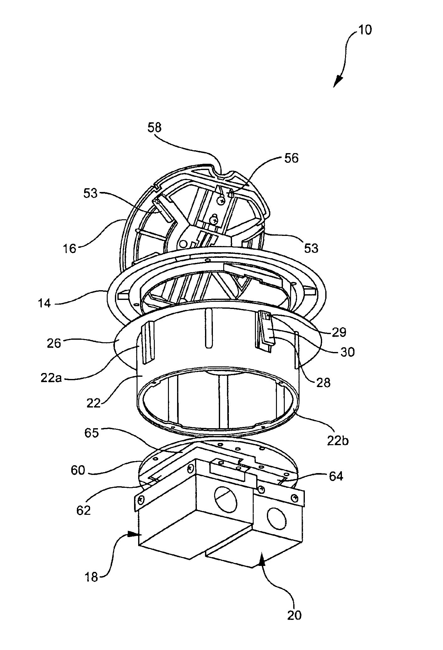
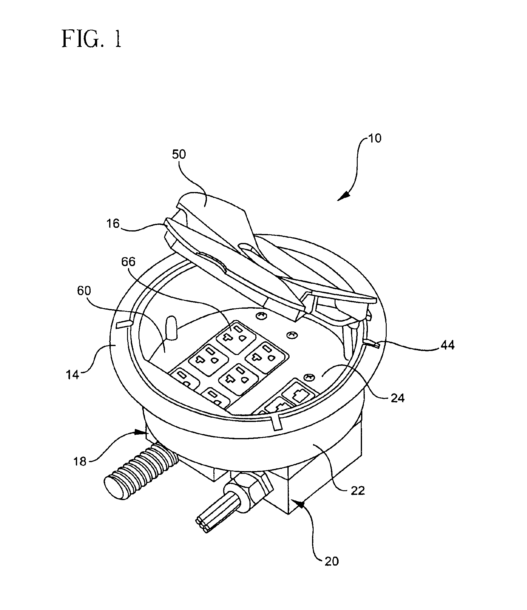
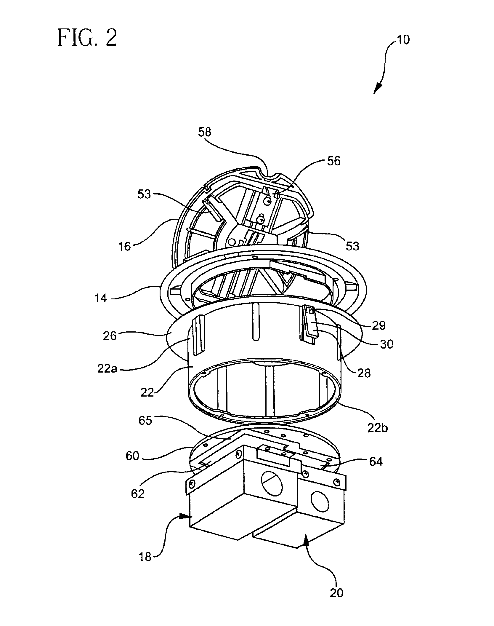
The present invention provides an electrical termination module which is preferably installable in a floor and houses electrical connections such as electrical outlets, and voice or data connectors. The present invention is particularly suitable for use in access floor applications where the floor surface is raised creating a space underneath. The electrical termination module may include one or more connection modules which are selectively employed in the field to accommodate particular connection requirements. The electrical termination module further provides water resistance features for protecting the connection modules from contamination.

Referring to FIGS. 1 to 3, electrical termination module 10 generally includes a side wall 22 attachable to a cover flange 14 to which a cover 16 is supported. A base plate 60 is secuarable to a lower end of side wall 22. A plurality of connection modules 18 and 20 which house electrical connectors are attachable to base plate 60. Side wall 22...


PUM


Abstract

An electrical termination module including a side wall having an upper end attachable to a flange, the flange having a central opening. A cover is pivotally supported on the flange and a base plate is removably securable to a lower end of the sidewall. A first connection module is removably attached to the base plate. The first connection module housing a plurality of first electrical connectors.

Description

FIELD OF THE INVENTIONThe present invention relates to an electrical termination module and more specifically an electrical termination floor module having a water resistant modular design.BACKGROUND OF THE INVENTIONIn office space and other commercial environments it is often desired to have access to electrical outlets or other electrical connections at locations located a distance from standard wall outlets. In order to safely accommodate such situations, floor boxes are typically used. These boxes may be located in the floor near or at the location, such as under a work cubicle or near a piece of machinery, where the connection is needed. The electrical connections may be electrical outlets, telephone jacks or data connections used for networking computers.The prior art includes floor boxes that may be fitted in openings formed in concrete floors often found in commercial building. Such boxes may be set in poured concrete floors, in which case there location is fixed once the co...

Claims


Application Information

Patent Timeline
Patent Type & Authority Patents(United States)
IPC IPC(8): H01R13/44H01R13/502H01R13/447H01R13/506
CPCH01R13/506H01R13/447
Inventor DRANE, MARK R.MICHAELIS, DANIEL K.
Owner THOMAS & BETTS INT INC
Why Eureka
Try Eureka