Double-sided adhesive tape dispenser

a dispenser and adhesive tape technology, applied in the field of adhesive tape dispensers, can solve the problem of low working performan

Inactive Publication Date: 2005-02-01
HO HUNG CHIEH
View PDF5 Cites 16 Cited by
  • Summary
  • Abstract
  • Description
  • Claims
  • Application Information

AI Technical Summary

Benefits of technology

The primary objective of the present invention is to provide a double-sided adhesive tape dispe

Problems solved by technology

When the user intends to use the conventional double-sided adhesive tape, the user has to adhere the adhesive side onto a wor

Method used


Image

  • Double-sided adhesive tape dispenser
  • Double-sided adhesive tape dispenser
  • Double-sided adhesive tape dispenser

Examples


Embodiment Construction

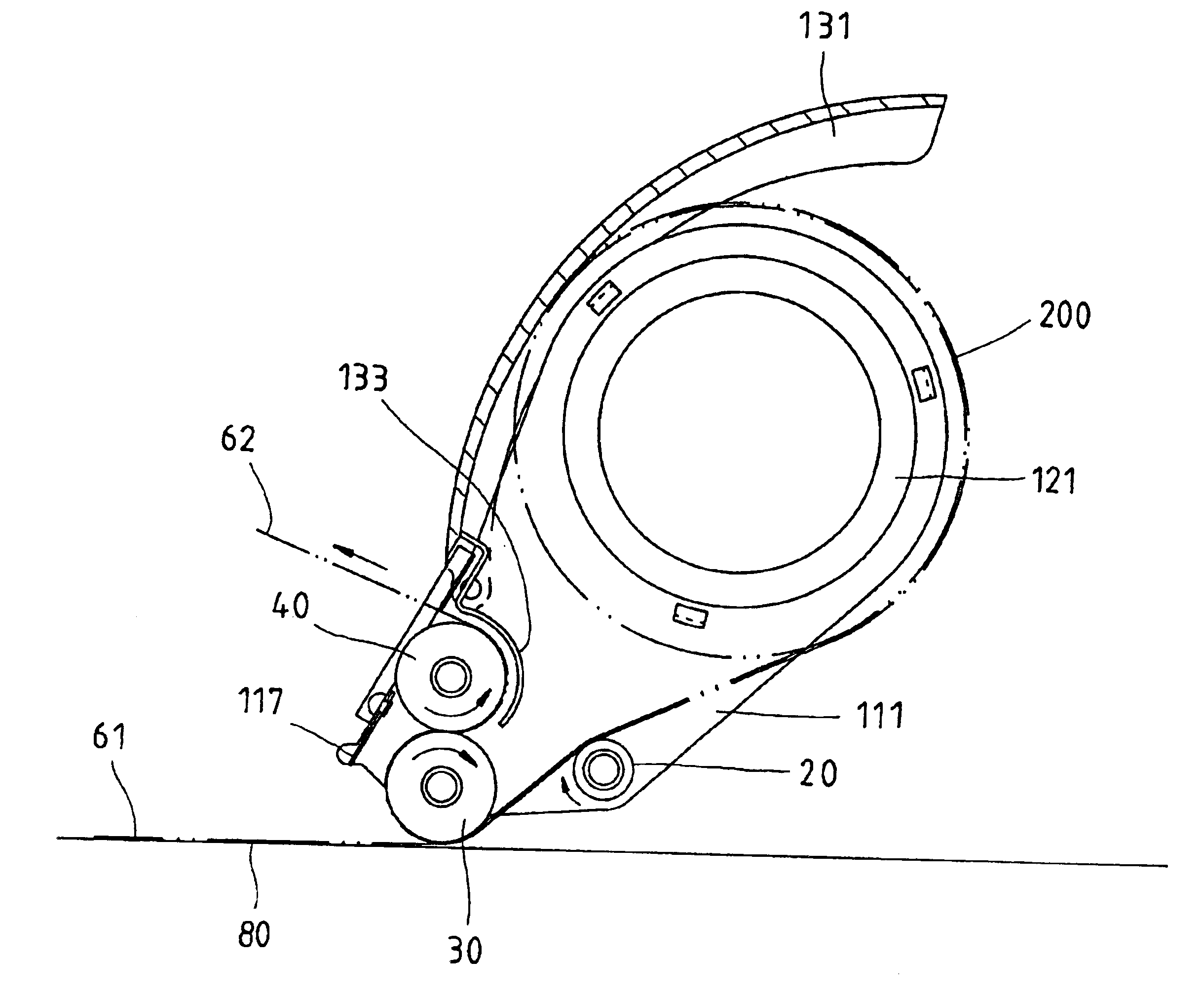
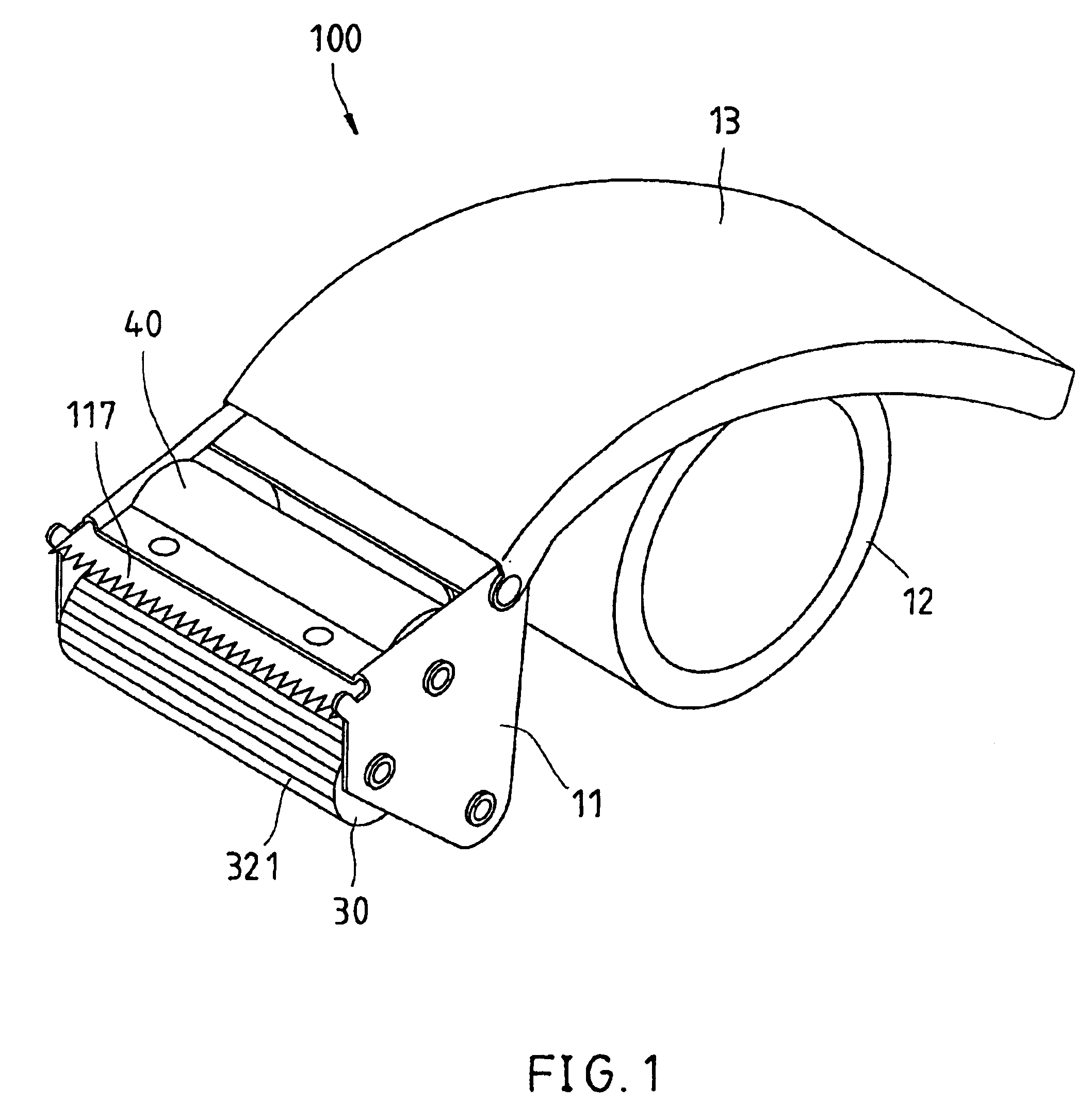
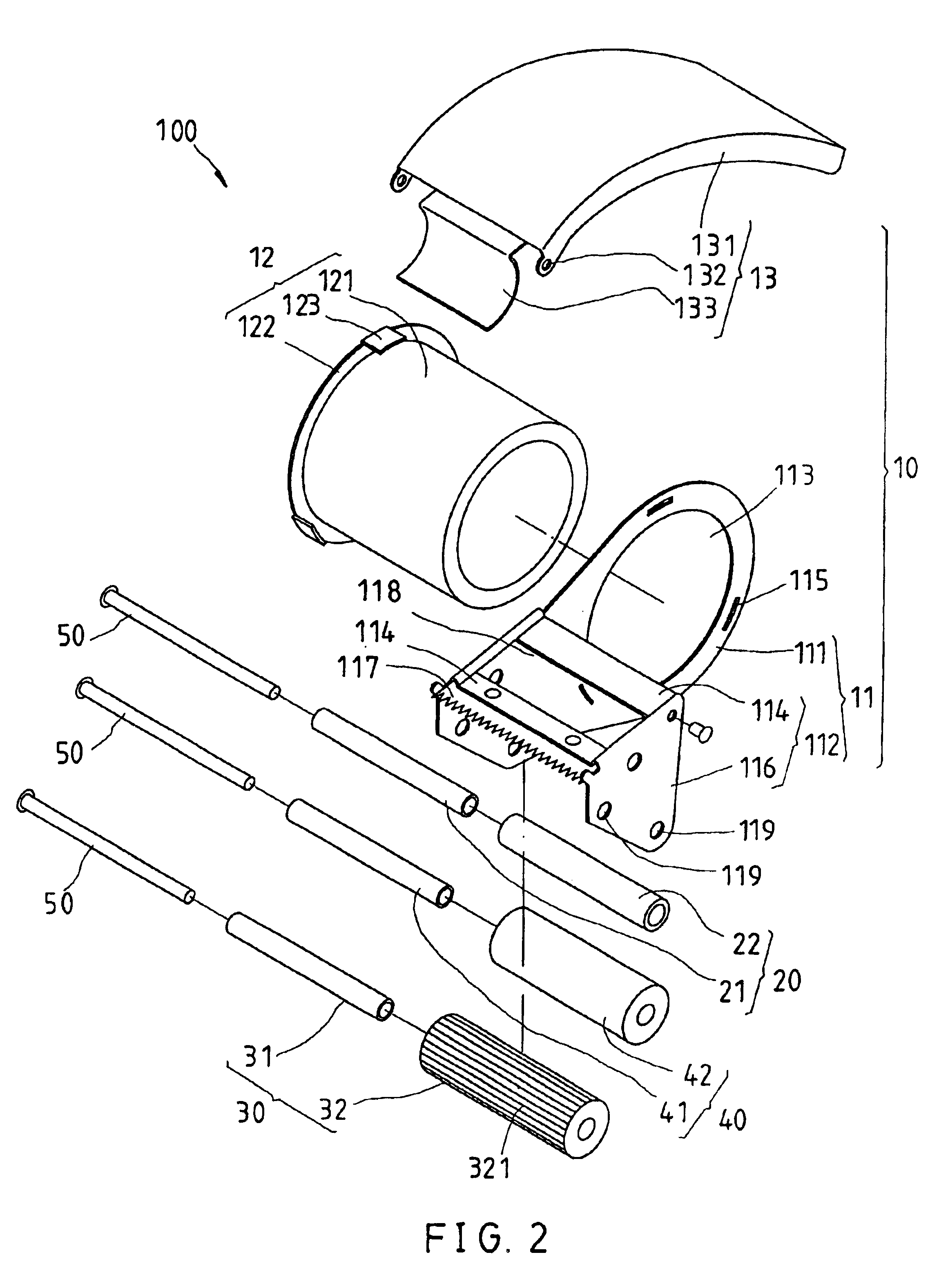
Referring to FIGS. 1-3, a double-sided adhesive tape dispenser 100 constructed according to a preferred embodiment of the present invention is composed of a main frame 10, an auxiliary roller 20, a guide roller 30, and a driven roller 40.

The main frame 10 includes a crane 11, a reel 12, and a handle 13.

The crane 11 is composed of a first frame member 111, a second frame member 112, and a cutter 117. The first frame member 111 has a circular hole 113 formed at a rear section thereof and a plurality of clamp holes 115 formed thereon around the circular hole 113. The second frame member 112 has two top plates 114 and a guard plate 116. The two top plates 114 are spaced apart and parallel to each other, each of which is perpendicularly connected with a front top edge of the first frame member 111 at an end thereof. The guard plate 116 is perpendicularly connected with the other ends of the two top plates 114 at a lateral edge thereof. Hence, the guard plate 116 is parallel to the first ...


PUM

PropertyMeasurementUnit
Angleaaaaaaaaaa

Abstract

A double-sided adhesive tape dispenser. The dispenser includes a main frame for mounting a rotatable adhesive tape roll thereon, a guide roller rotatably mounted on the main frame, and a driven roller rotatably mounted on the main frame. The driven roller is parallel to the guide roller and has an outer surface contacting an outer surface of the guide roller such that the driven roller is driven to roll by the guide roller.

Description

BACKGROUND OF THE INVENTION1. Field of the InventionThe present invention relates generally to adhesive tape dispensers, and more particularly, to a double-sided adhesive tape dispenser.2. Description of the Related ArtGenerally, there are two kinds of adhesive tapes; one is single-sided adhesive tape which one side is disposed with adhesive and the other side is glare to be easily split; the other is double-sided adhesive tape which two sides are both disposed with adhesive and an isolation film having a glare surface and covered on one of the adhesive sides to enable the tape to be easily rolled. When the user intends to use the conventional single-sided adhesive tape, the user can directly adhere the adhesive side onto a workpiece. When the user intends to use the conventional double-sided adhesive tape, the user has to adhere the adhesive side onto a workpiece and then uptear and remove the isolation film, wherein the latter action is redundant to cause low working performance.S...

Claims


Application Information

Patent Timeline
IPC IPC(8): B44C7/00B65H35/06B65H35/07
CPCB65H35/0033B65H37/005Y10T156/18Y10T156/1348Y10T156/1365Y10T156/1795Y10T225/282Y10T225/257
Inventor HO, HUNG-CHIEH
Owner HO HUNG CHIEH
Why Eureka
Try Eureka