Quick attachment SMA connector

a technology of sma connector and quick attachment, which is applied in the direction of coupling device connection, two-part coupling device, electrical apparatus, etc., can solve the problems of time-consuming installation and negatively affecting electrical and mechanical performan

Inactive Publication Date: 2005-02-01
COMMSCOPE TECH LLC
View PDF17 Cites 55 Cited by
  • Summary
  • Abstract
  • Description
  • Claims
  • Application Information

AI Technical Summary

Problems solved by technology

While existing connectors work relatively well, they are time consuming to install.
In addition, temperature cycling and / or rotational torque applied to the cable assembly can cause the threaded nut to back-off below the minimum torque value required, negatively impacting electrical and mechanical performance.

Method used


Image

  • Quick attachment SMA connector
  • Quick attachment SMA connector
  • Quick attachment SMA connector

Examples


Embodiment Construction

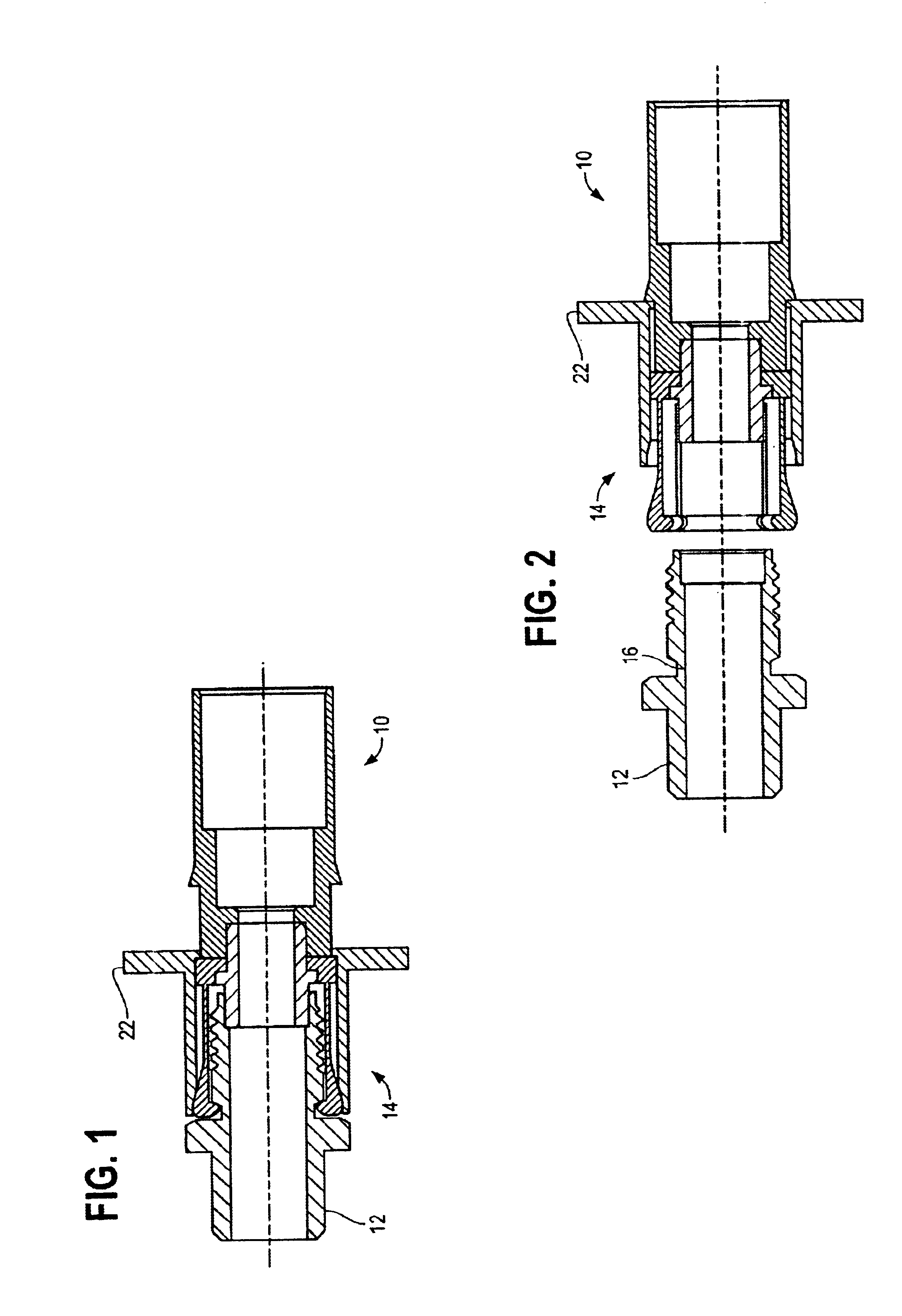
FIGS. 1 and 2 are a cut-away side views of a quick attachment coaxial connector combination 10, shown generally under an illustrated embodiment of the invention. FIG. 1 shows a female portion 12 engaged with the male portion 14. FIG. 2 shows the female portion 12 disengaged from the male portion 14.

Under the illustrated embodiment, a laterally sliding collar 22 is used to lock or unlock the connector combination 10. As used herein, a laterally sliding collar refers to a collar that locks the male portion 14 to the female portion 12 by virtue of its sliding motion along an axis of engagement of the connectors. It does not refer to connectors (e.g., BNC connectors) where the collar has a receptacle to accept and lock with a peg on an opposing portion of the connector as a direct result of twisting the collar.

Sliding the collar 22 to the left 21 (as shown in FIG. 1) locks the male portion 14 to the female portion 12. Sliding the collar to the right 23 (as shown in FIG. 2) allows for th...


PUM


Abstract

A coaxial connector combination is provided having a male and a female portion. The coaxial connector combination includes a female portion having a tubular body with an engagement end and an annular locking groove disposed around an outer surface of the tubular body spaced back from the engagement end and a male portion. The male portion further includes a sleeve, a plurality of pawls, each extending outwards from an engagement end of the sleeve to form an annulate of spaced-apart pawls disposed around a center axis of the sleeve, said annulate of pawls being adapted to engage the outer surface of the tubular body and wherein a catch on an engagement end of each pawl of the plurality pawls engages the annular groove of the female portion and a locking collar disposed around an outside surface of the plurality of pawls and adapted to slidably lock the catches of the distal end of the plurality of pawls into the annular locking groove.

Description

FIELD OF THE INVENTIONThe field of the invention relates to radio frequency communication systems and more particularly to radio frequency connectors.BACKGROUND OF THE INVENTIONCoaxial connectors for radio frequency (rf) signals are known. Such connectors are typically used with a coaxial cable containing an external conductor / shield surrounding one or more internal conductors. The coaxial connector functions to align and provide an electrical path to the respective ends of the conductors while providing a continuous shield to minimize rf leakage.The alignment and attachment of the conductors within some rf connectors (e.g., SMA connectors, by Amphenol, Inc.) occurs via operation of a conductor interface. A conductor interface is a precision coupler within the SMA connector that allows opposing conductors to be inserted from each end and brought into alignment and attached via operation of the connector.The SMA connector includes a female portion and a male portion. The male portion...

Claims


Application Information

Patent Timeline
Patent Type & Authority Patents(United States)
IPC IPC(8): H01R13/00H01R13/627H01R13/646H01R9/05
CPCH01R24/40H01R13/6277H01R9/05H01R2103/00
Inventor MCMULLEN, NORMANFERDINA, JEFF
Owner COMMSCOPE TECH LLC
Why Eureka
Try Eureka