Golf tee

a golf tee and tee technology, applied in the field of golf tees, can solve the problems of unsuitability for reuse and difficult restoration

Inactive Publication Date: 2005-02-01
WANG AUSTIN
View PDF5 Cites 21 Cited by
  • Summary
  • Abstract
  • Description
  • Claims
  • Application Information

AI Technical Summary

Problems solved by technology

Or, once being bent and deformed, it is difficult to be restored and therefore unsuitable to be reused.

Method used


Image

  • Golf tee
  • Golf tee
  • Golf tee

Examples


Embodiment Construction

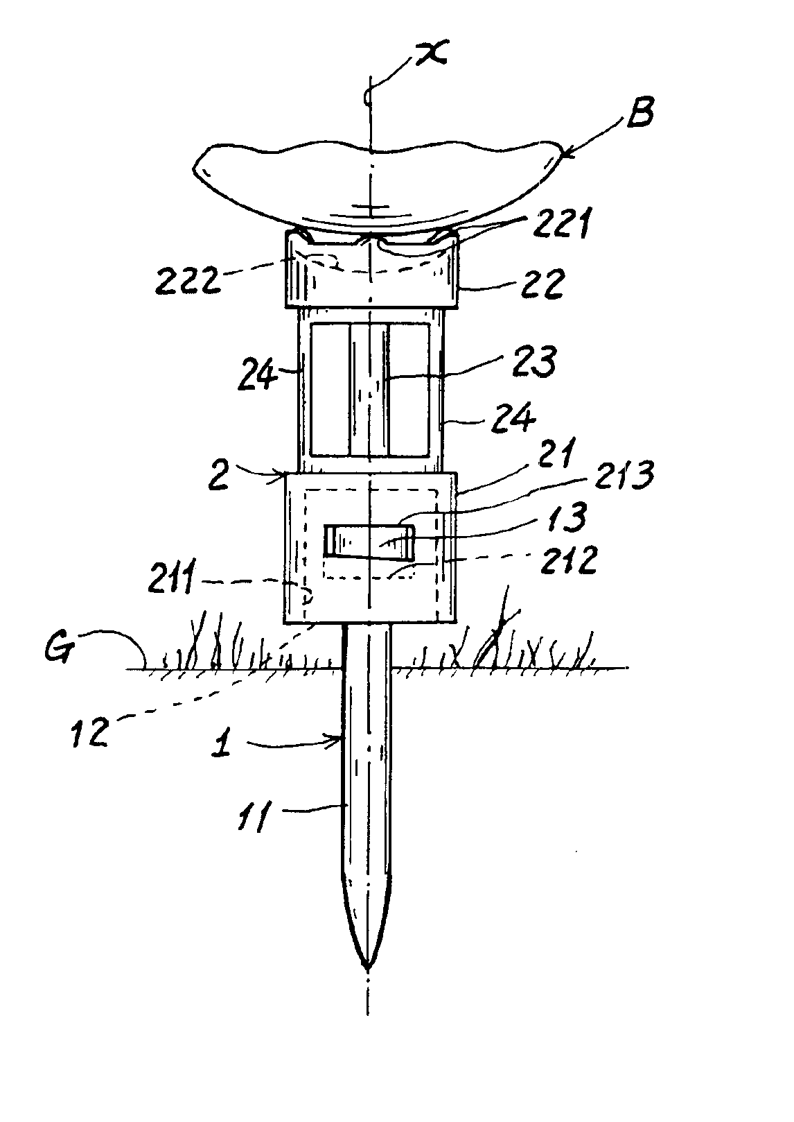
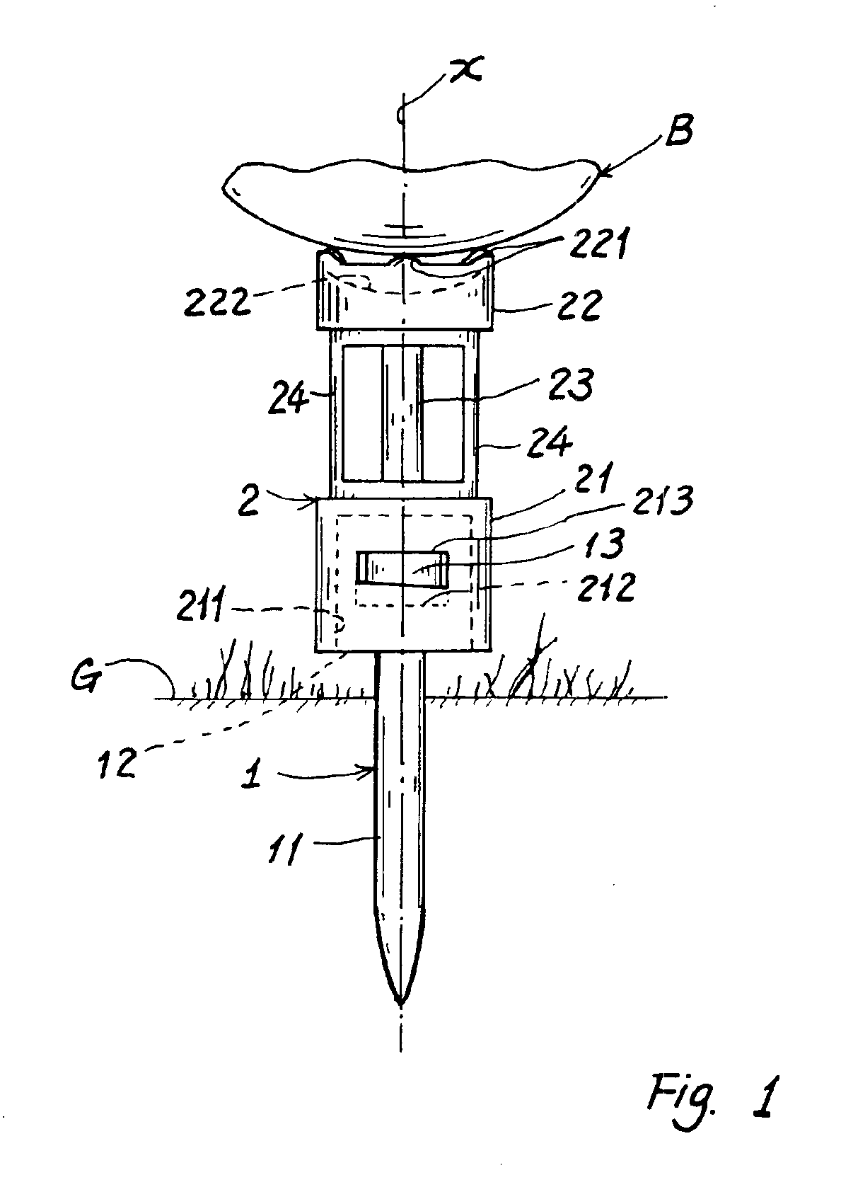
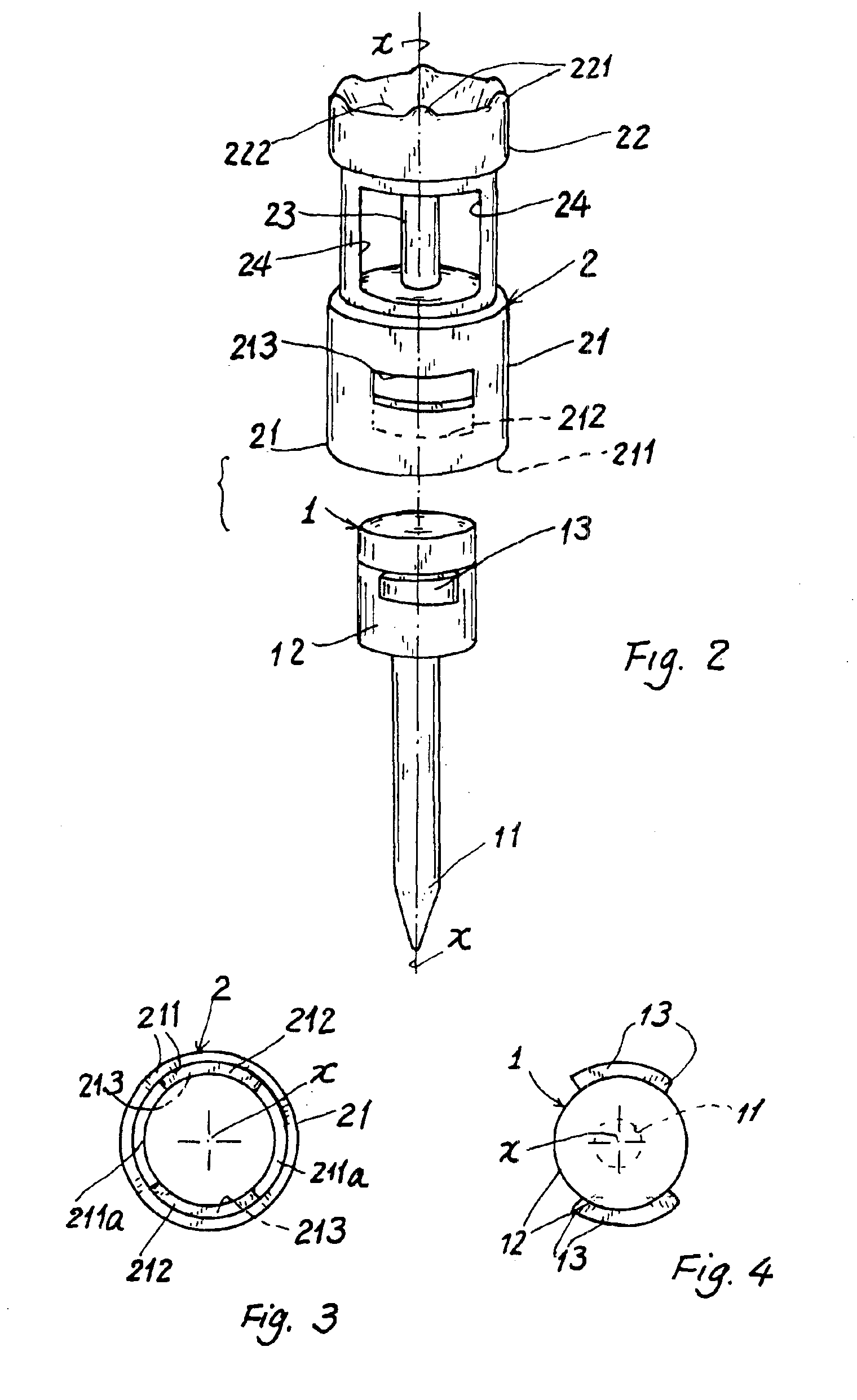
As shown in the drawing figures, a golf tee of the present invention comprises: a peg member 1 inserted in the ground G; and a flexible holding member 2 engageably mounted on the peg member 1 for holding a golf ball B thereon. A longitudinal axis X is defined at a longitudinal center of the golf tee when coupling the holding member 2 with the peg member 1.

The peg member 1 includes: a peg 11 inserted in the ground, a head portion 12 formed on an upper portion of the peg 11, and a pair of lugs 13 circumferentially formed on the head portion 12 to be engaged with the flexible holding member 2.

Each lug 13 may be formed as a wedge or an angled block in order to be engageable with a corresponding counter-part (a slot) formed in the flexible holding member 2.

The peg member 1 is integrally formed by any plastic molding process and may be made of rigid plastic or composite materials to be firmly inserted into the ground.

The flexible holding member 2 is integrally formed with flexible resilie...


PUM


Abstract

A golf tee includes: a peg member inserted into the ground; and a flexible holding member engageably mounted on the peg member having a seat portion for holding a golf ball thereon, a coupling base for engaging the peg member therewith, and a plurality of links connected between the seat portion and the coupling base; whereby upon driving of the golf ball off the seat portion as struck by a club head, the flexible holding member may be temporarily biased for absorbing the striking force partially acting upon the golf tee and then the flexible holding member will be restored upright automatically to thereby be repeatedly reusable.

Description

BACKGROUND OF THE INVENTIONU.S. Pat. No. 5,242,170 to Richard E. Ward disclosed a golf tee comprising a lower piece having a spike inserted into the ground, and an upper piece mounted on an upper portion of the lower piece having a retainer shaft (22) extending upwardly into the upper piece from the spike.However such a prior art has the following drawbacks:1. The sleeve (26) of the upper piece should be made of flexible material, which however may be bent, twisted or deformed once loaded with a golf ball thereon to thereby influence the supporting stability and the flying orientation of the ball when struck by a club head.2. The retainer shaft (22) is integrally formed with the ground spike (14) which is made with rigid material. So, the shaft (22) may be easily broken to thereby shorten its life cycles. Or, once being bent and deformed, it is difficult to be restored and therefore unsuitable to be reused.The present inventor has found the drawbacks of the conventional golf tee and...

Claims


Application Information

Patent Timeline
Patent Type & Authority Patents(United States)
IPC IPC(8): A63B57/00
CPCA63B57/0018A63B57/10
Inventor WANG, AUSTIN
Owner WANG AUSTIN
Why Eureka
Try Eureka