Portable radiometry and imaging apparatus

a radiometry and imaging apparatus technology, applied in the direction of optical elements, instruments, optical radiation measurement, etc., can solve the problems of affecting the normal vision of the patient, and causing lethal heat, so as to achieve enhanced vision, easy installation and removal, and enhanced vision

Inactive Publication Date: 2005-02-01
TELEDYNE FLIR LLC
View PDF43 Cites 96 Cited by
  • Summary
  • Abstract
  • Description
  • Claims
  • Application Information

AI Technical Summary

Benefits of technology

[0008]A head-up display, an infrared (IR) camera and associated electronics including power are integrated into portable, self-contained, wrap-around, face-wom vision-enhancement apparatus useful in environments of dense air-bome particulate and thermal extremes such as encountered in fire fighting situations, in accordance with the invention. Reflective and opaque expanses or lenses are provided in front of a user's eyes at approximately eye level for IR vision display and blinding purposes, respectively, to produce a clear bright picture or image representing a detected and imaged scene viewed by the camera otherwise obscured by darkness or obscurants. The IR camera is integral with the wraparound system along with a self-contained power supply so that the system is portable and requires no umbilical cord or other external connections. The imager is preferably an uncooled focal plane array. Associated imaging, storing, processing and displaying electronics are cooled in the extreme thermal environment using an integral plural phase heatsink, to protect elements of the apparatus from environmental heat.
[0009]The apparatus is separate from, but compatible with, helmets and SCBA and attire worn by the user so that it can easily be installed and removed by an individual user. Extended hands-free operation is provided in a lightweight package providing enhanced vision via color-coded temperature banding for display purposes, the color coding being performed in nmicroprocessor-based fminware that forms part of the electronics. The apparatus may be temporarily affixed via a clip and strap to the brim of a helmet and may be easily shifted on the user's face from its normal night-vision position to a temporary stowed position in front of the forehead whereby the user has virtually unobstructed binocular vision. The intended use of the apparatus is for firefighting and fire rescue, but it is believed to have application in other rescue and adverse conditions, associated with vehicle accidents, mining accidents, and combat.

Problems solved by technology

Fire fighting is extremely hazardous and demanding because of extreme temperatures and obscurants that can blind or disable a fire fighter from locating the fire's source or human beings at risk within a burning building.
When there are no visible flames, e.g. when alcohol, hydrogen, hydrocarbons, etc. burn, there can be lethally high temperatures caused by gases that burn without visible ignition or flaming.
Whether there are visible or invisible flames, nevertheless there can be dense smoke or airborne particulate that makes normal vision impossible.
Other vision systems for fire detection are not designed for hands-free operation as is required of a system used by firefighters that must enter the scene of the fire.
So-called night vision systems relying on IR detection and imaging often are useless in the presence within the detector's field of view of such extreme temperatures that the location of a human being or animal, for example, in a burning building goes undetected by a display phenomenon called blooming whereby a high-temperature gas cloud is represented by a color, e.g. white, that tends to wash out critical detail such as a low-temperature temperature human form represented in another area of the display by a different gray scale.
For example, the video systems of U.S. Pat. No. 5,200,827, the disclosure of which is incorporated herein by reference, do not address these problems unique to the firefighting and rescue fields.

Method used


Image

  • Portable radiometry and imaging apparatus
  • Portable radiometry and imaging apparatus
  • Portable radiometry and imaging apparatus

Examples


Embodiment Construction

front of the user.

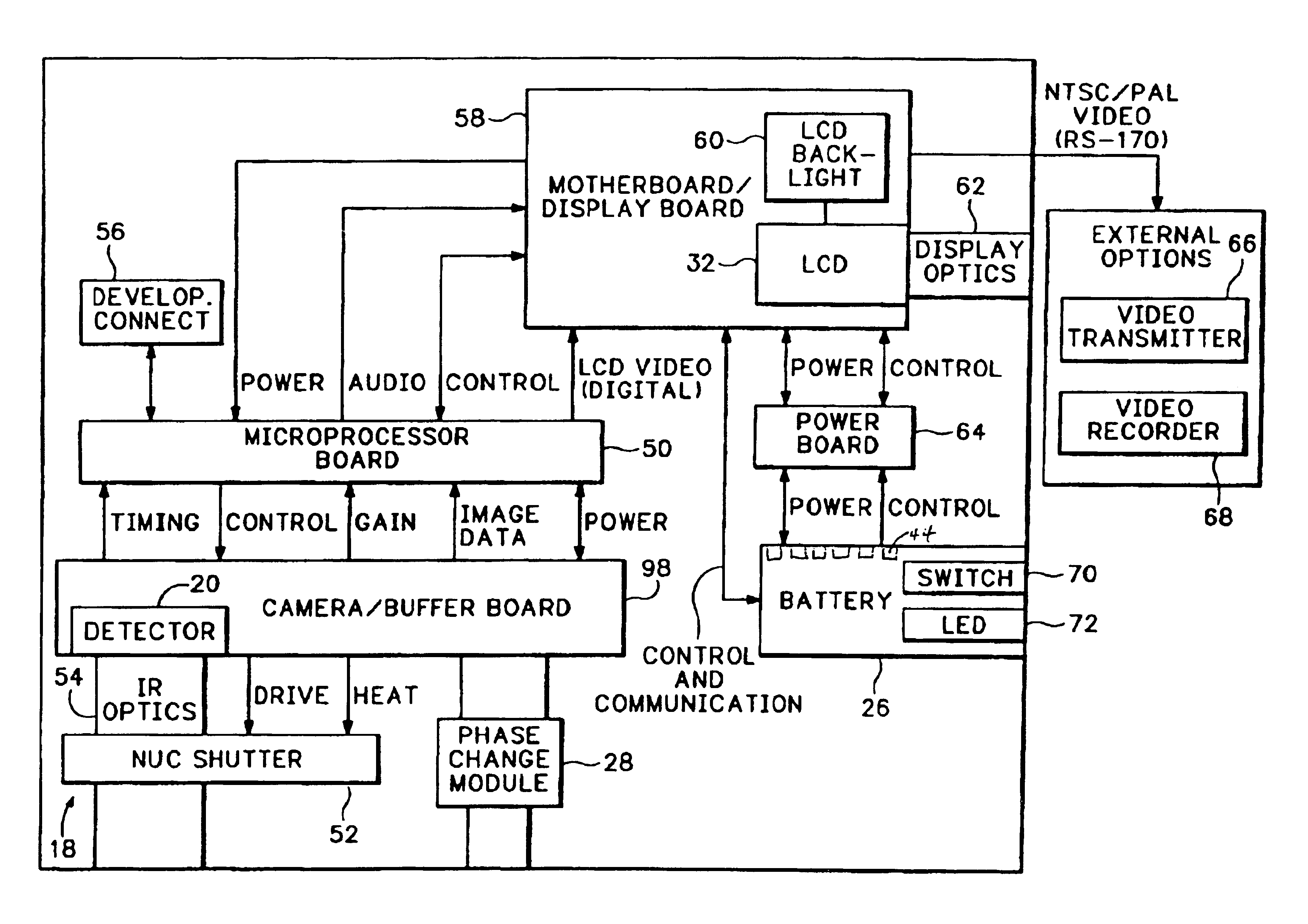
[0015]FIG. 5 is a block diagram of the opto-electronics within the housing of the invented appa.

[0016]FIG. 6 is a flowchart illustrating the color mapping method used in the invented apparatus for image enhancement

[0017]FIGS. 7A and 7B are graphs at illustrate the color mapping method used in the invented apparatus for image enhancement, with FIG. 7A showing an entire palette mapped, and with FIG. 7B showing a detail of a portion of FIG. 7A.

DETAILED DESCRIPTION OF THE PREFERRED EMBODIMENT AND BEST MODE OF CARRYING OUT THE INVENTION

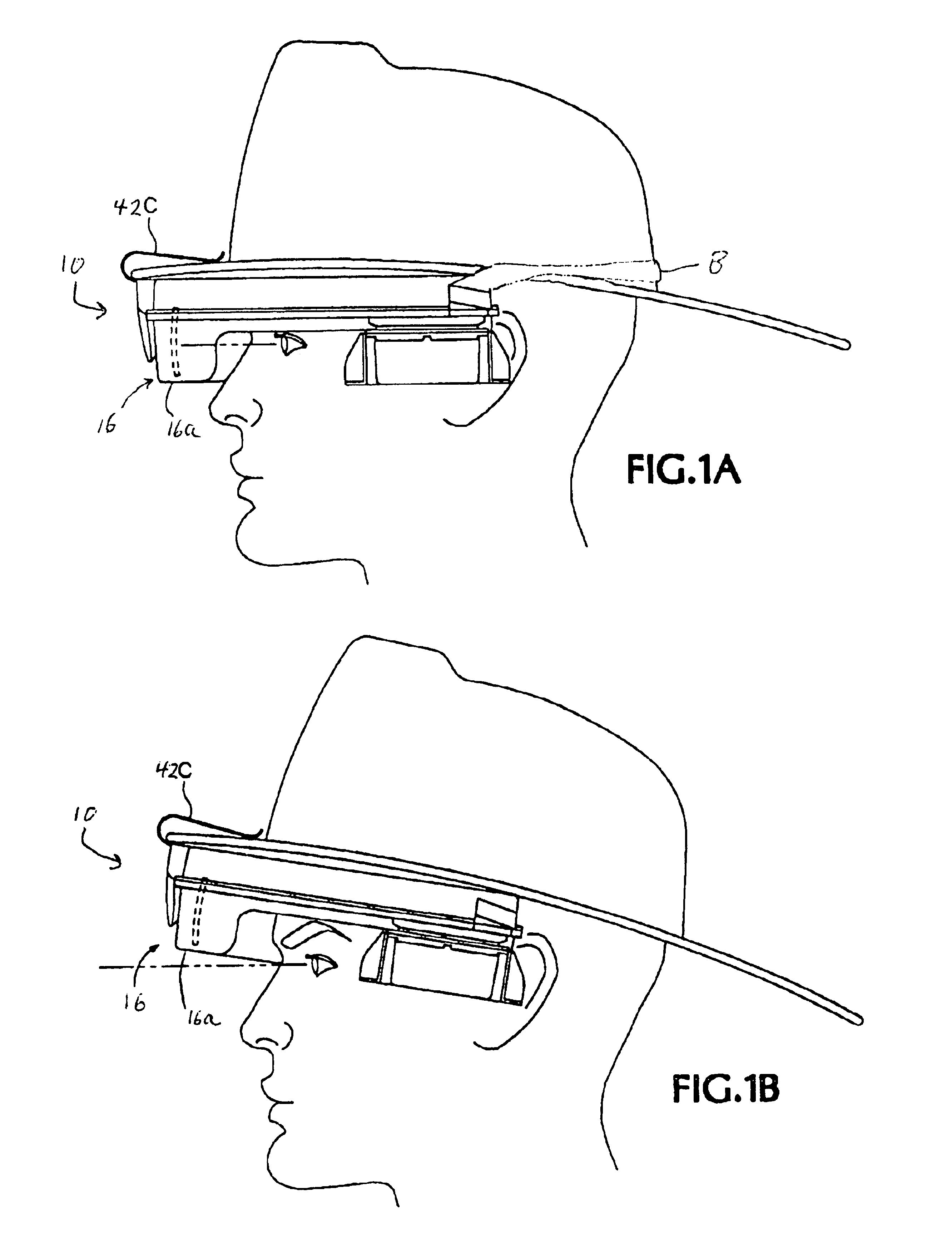
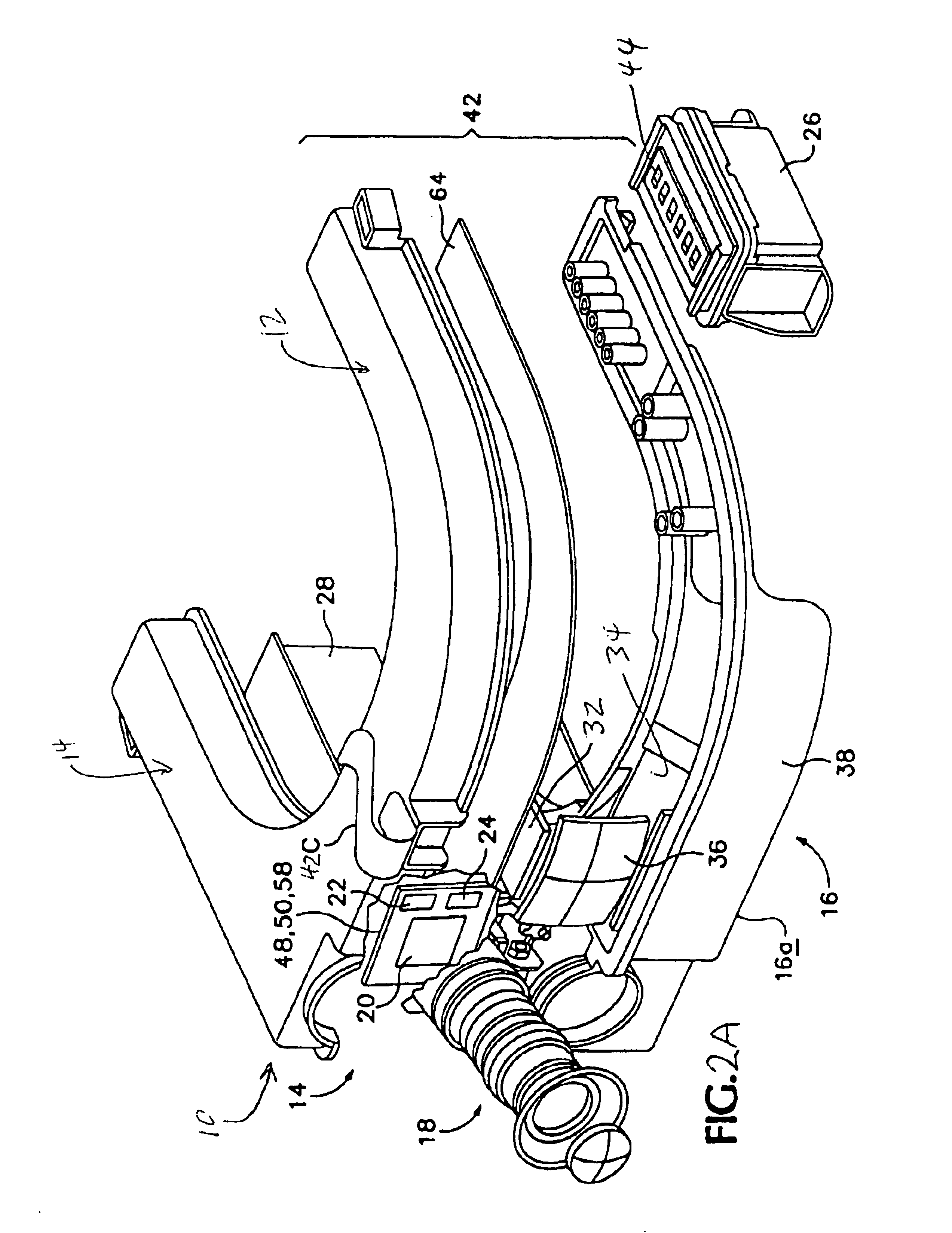
[0018]Referring first to FIGS. 1A, 1B, 2A and 2B, a preferred embodiment of the invented wrap-around, head-up display apparatus is indicated generally at 10. Apparatus 10 may be seen to include a left arching region 12, a right arching region 14 and a forward arching region 16 that hovers preferably just above the user's eye level on the face. Apparatus 10 preferably includes a lightweight, preferably molded polymer housing with an interi...


PUM


Abstract

An infrared (IR) camera and associated electronics including power are integrated into portable, self-contained, vision-enhancement apparatus useful in environments of dense air-borne particulate and thermal extremes such as encountered in fire fighting situations, in accordance with the invention. The IR camera is integral with a self-contained power supply so that the system is portable and requires no umbilical cord or other external connections. The camera includes an imager that is preferably an un-cooled focal plane array, and associated imaging, storing, processing and displaying electronics that are cooled in the extreme thermal environment using an integral plural phase heatsink.

Description

CROSS-REFERENCE TO RELATED APPLICATION[0002]This application is a continuation-in-part of U.S. patent application Ser. No. 09 / 210,167, filed Dec. 11, 1998, now U.S. Pat. No. 6,255,650, which is hereby incorporated by reference.TECHNICAL FIELD[0003]The present invention relates generally to hazard-avoidance and blind vision equipment for use in extreme temperatures. More particularly, it concerns a self-contained, portable, easily deployed, helmet-mounted thermal or infrared (IR) imaging system capable of unobtrusively expanding the view of users such as fire fighters by providing a head-up IR detecting and imaging of a scene in front of a user, displaying an image that eliminates or sees through obscurants such as dark, smoke and particulate that may otherwise blind the user.BACKGROUND ART[0004]Fire fighting is extremely hazardous and demanding because of extreme temperatures and obscurants that can blind or disable a fire fighter from locating the fire's source or human beings at r...

Claims


Application Information

Patent Timeline
Patent Type & Authority Patents(United States)
IPC IPC(8): G02B27/01G02B23/00G02B23/12G02B27/00
CPCG02B23/125G02B27/017G02B2027/0138G02B2027/0118G02B2027/0123G02B2027/0112
Inventor WARNER, CHARLES C.FOSTER, SCOTT A.EVANS, STEWART W.KRIVOY, RAULBURKE, MICHAEL W.RAE, JOHN R.
Owner TELEDYNE FLIR LLC
Why Eureka
Try Eureka