Guide plate
- Summary
- Abstract
- Description
- Claims
- Application Information
AI Technical Summary
Benefits of technology
Problems solved by technology
Method used
Image

Examples
first embodiment
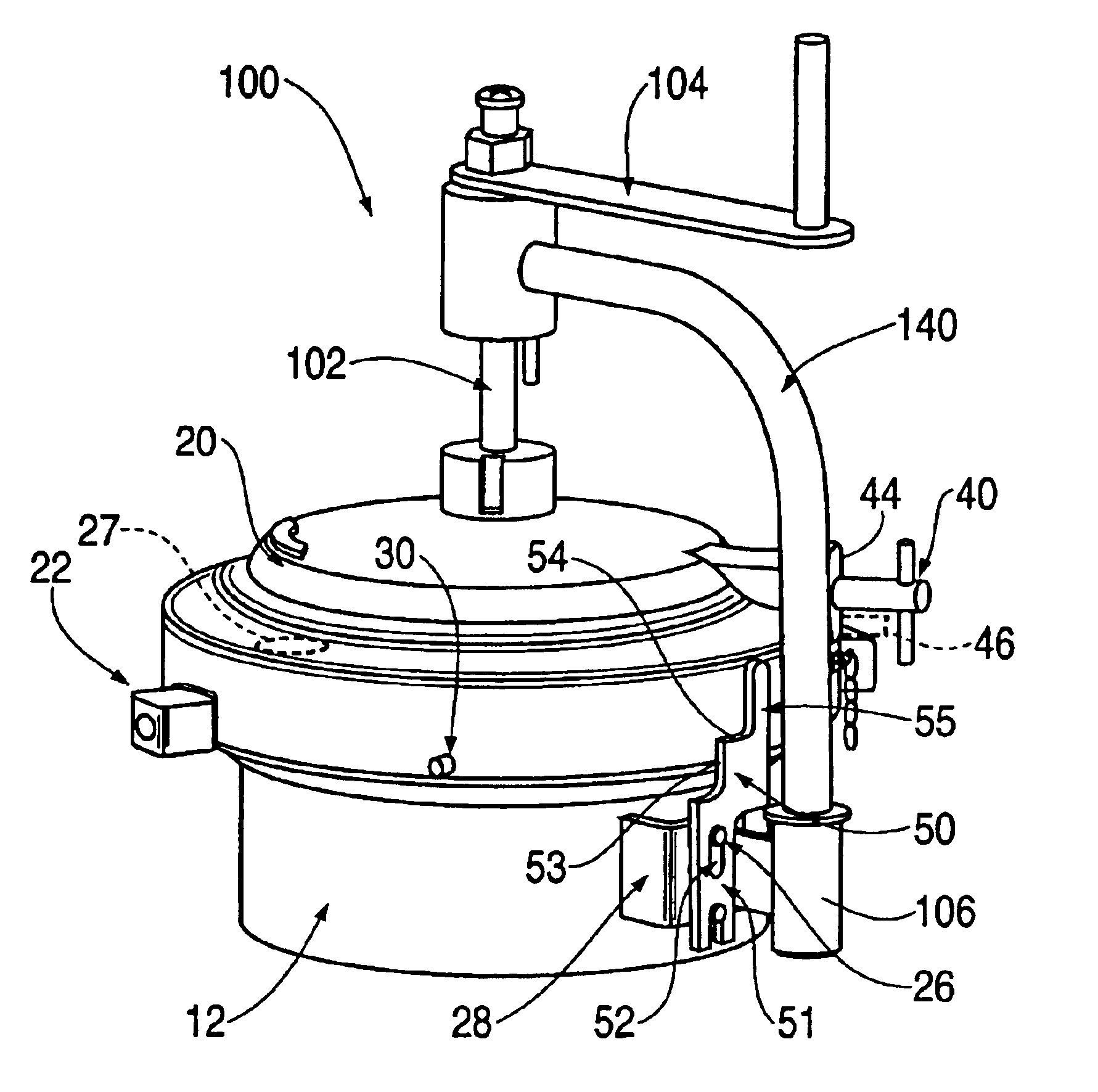
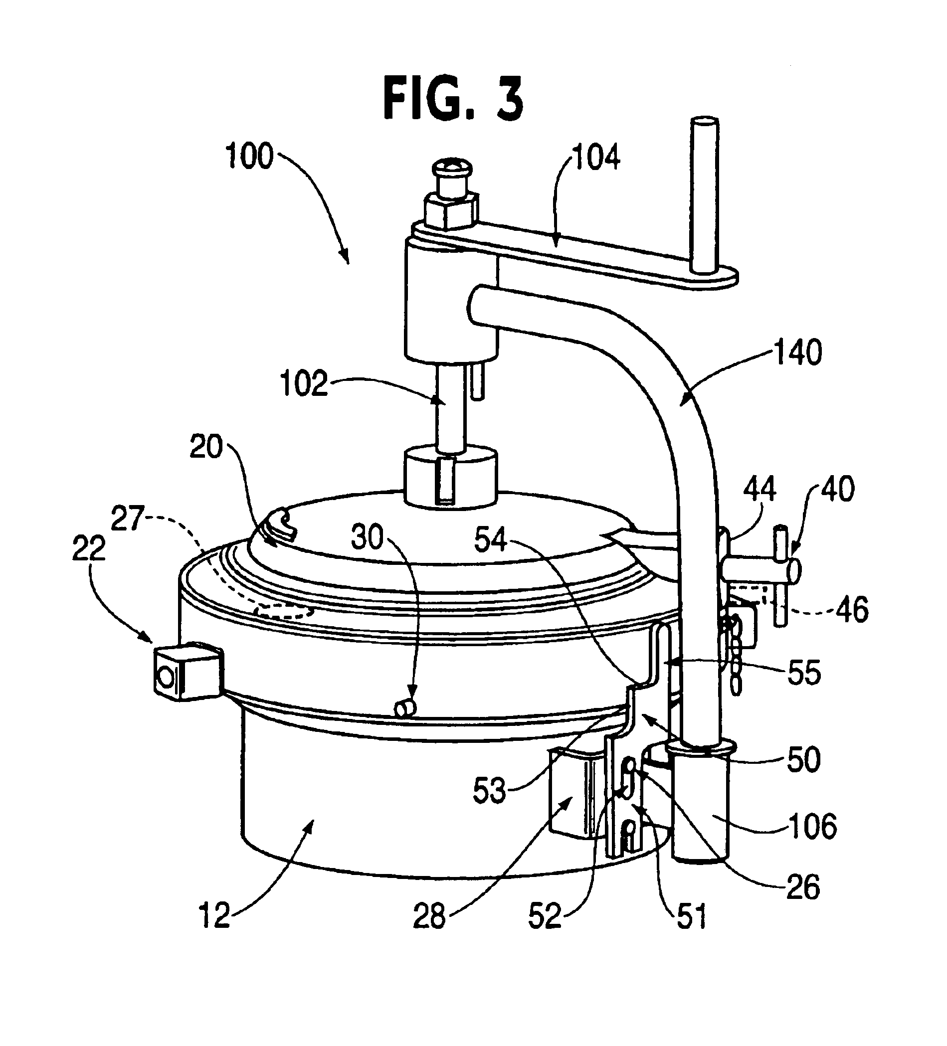
FIG. 3 shows a closure arrangement 100 of the invention comprising a head 20, a hub 12, a pressure release device 40, an actuating means for lifting the head 20 vertically, and a means for supporting the head 20 when it is not on the hub 12. The closure arrangement 100 further comprises a marker pin 30 and a guide plate 50.
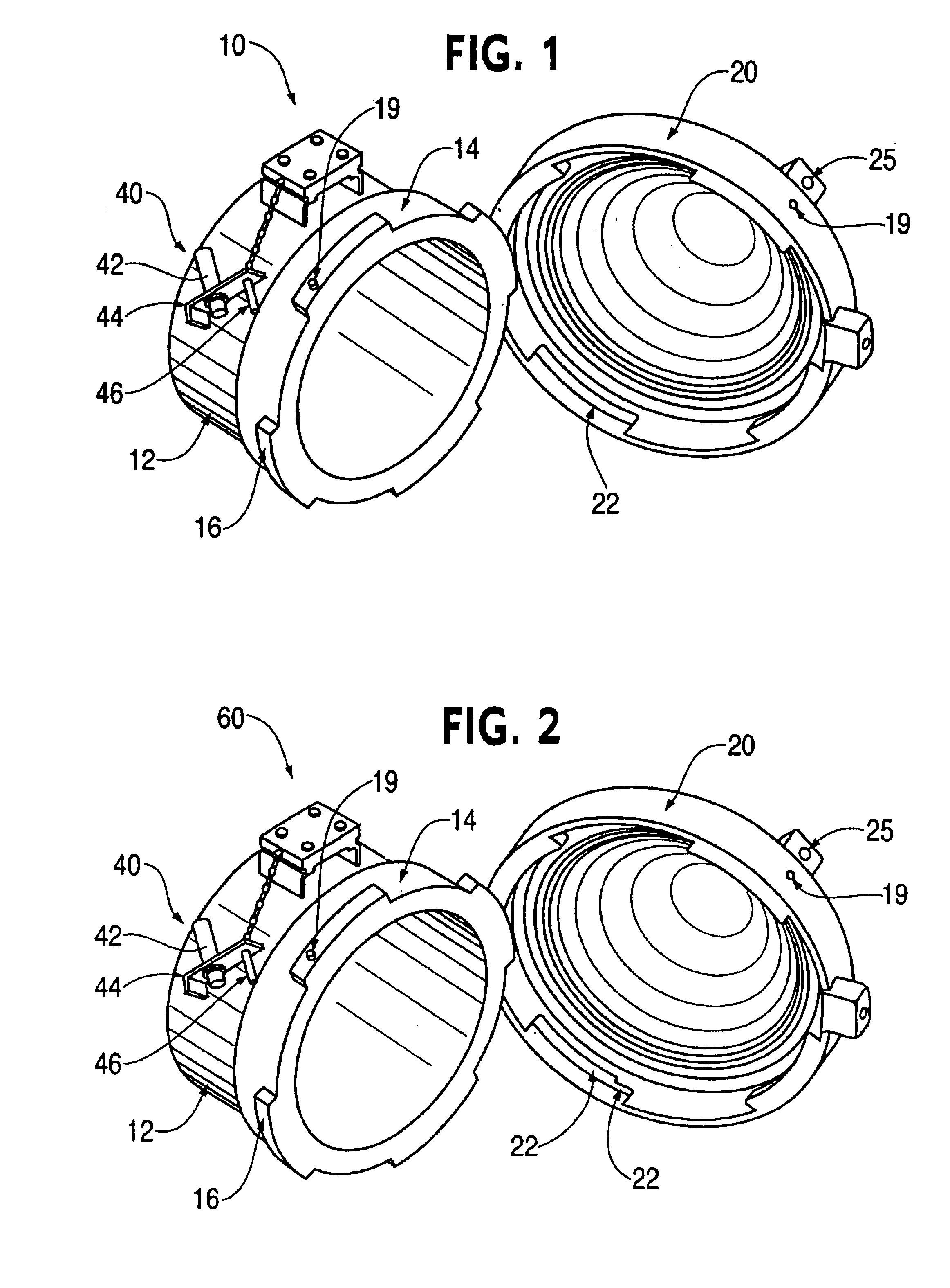
The head 20 and hub 12 are generally similar to those illustrated in FIG. 2. The head 20 comprises a set of four lugs 22 and a set of four stepped lugs 24, and the hub 12 comprises a flange 14 with a set of four lugs 16. The head also comprises two diametrically opposite handles 27, which aid the user rotate the head 20 relative to the hub 12. The pressure release device 40 comprises a pressure release screw 42 that is rotatably connected to a deflector plate 44. Attached to the deflector plate 44 is a locking pin 46 projecting from the deflector plate 44 in a direction parallel to the pressure release screw 42.
The support means comprises a hinged davit arm 140 th...
second embodiment
FIG. 5 is a view of a horizontally orientated closure arrangement 200 of the invention. The closure arrangement 200 comprises a head 20, a hub 12, a pressure release device 40, and support means for supporting the head 20 when it is not on the hub 12. The closure arrangement further comprises a marker pin 30 and a guide plate 50.
The head 20 and hub 12 are generally similar to those illustrated in FIG. 2. The head 20 comprises a set of four lugs 22 and a set of four stepped lugs 24, and the hub 12 comprises a flange 14 with a set of four lugs 16. The pressure release device 40 comprises a pressure release screw 42 that is rotatably connected to a deflector plate 44. Attached to the deflector plate 44 is a locking pin 46 projecting from the deflector plate 44 in a direction parallel to the pressure release screw 42.
The support means comprises a hinged davit arm 240 that is connected to at one end to a fitting 212 that is journaled to a shaft 206. The shaft 206 is connected to the head...
PUM
 Abstract
Description
Claims
Application Information
 - R&D Engineer
- R&D Manager
- IP Professional
- Industry Leading Data Capabilities
- Powerful AI technology
- Patent DNA Extraction
Browse by: Latest US Patents, China's latest patents, Technical Efficacy Thesaurus, Application Domain, Technology Topic.
© 2024 PatSnap. All rights reserved.Legal|Privacy policy|Modern Slavery Act Transparency Statement|Sitemap