
Fire door lock mechanism

a door lock and door lock technology, applied in building locks, floor fabrics, constructions, etc., can solve the problems of unfavorable fire spreading through the open fire door to other unintentional places, and the user's hands are irritated, so as to facilitate fire safety and safety

Inactive Publication Date: 2005-02-15
LIN CHING TIEN
View PDF8 Cites 68 Cited by
  • Summary
  • Abstract
  • Description
  • Claims
  • Application Information

AI Technical Summary

Benefits of technology

An objective of the present invention is to provide a fire door lock mechanism which allows users to depress a handlebar in a vertical direction with respect to a first door mounted with the fire door lock mechanism to activate a lock bolt in a comfortable manner to open the first door.
Another objective of the invention is to provide a fire door lock mechanism which allows the fire door lock mechanism to automatically remain in a locked state when a high temperature is detected during a fire, making a fire door mounted with the fire door lock mechanism unable to be opened to prevent the fire from hurting people and spreading.
Furthermore, a partition having a protruding arm and a fire piece are coupled to the glide mount. The fire piece melts at a high temperature during a fire, making the partition shifted upwards by means of a force from an elastic member connected thereto and engaged with the lock bolt, such that the door lock mechanism is maintained in a locked state and cannot be disengaged by depressing the handlebar, thereby facilitating the fire security and safety.

Problems solved by technology

Further, the horizontal movement of the handlebar 11 makes the travel direction of the handlebar 11 different from that of the hands of the user, which causes discomfort to the hands of the user when operating the door lock.
Besides, when the above conventional door lock is in use, due to no provision of elements for a fire security purpose, therefore the door lock is not allowed to prevent the relief of a locked state during a fire, making users who are not aware of the fire still able to open the fire door and thus in danger, and also making the fire undesirably spread through the opened fire door to other unintended places.

Method used


Image

  • Fire door lock mechanism
  • Fire door lock mechanism
  • Fire door lock mechanism

Examples


Embodiment Construction

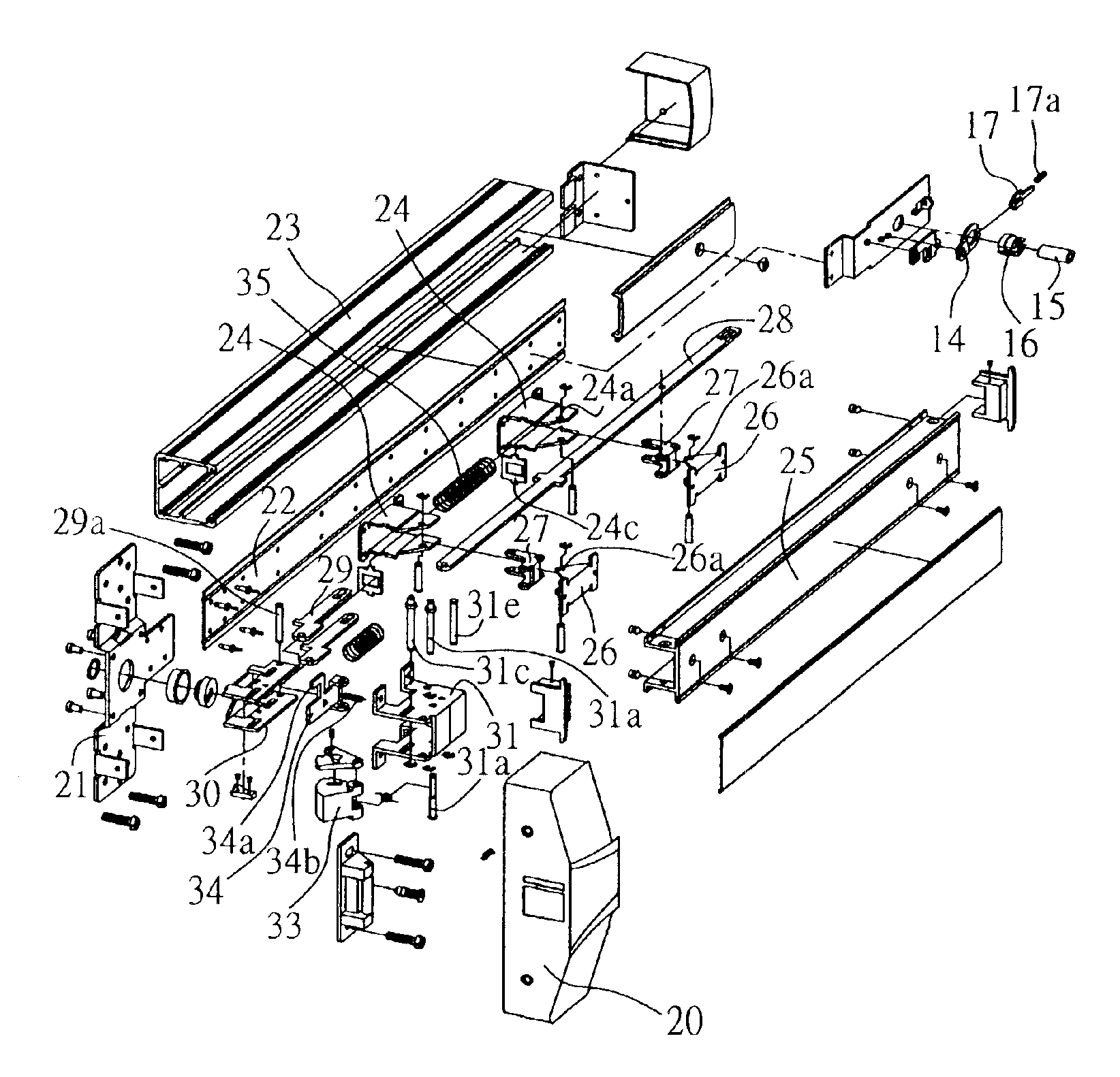
Please refer to FIGS. 4A to 4D showing the main structure of a fire door lock mechanism proposed by the present invention. This fire door lock mechanism comprises: a body 2 formed with a handlebar 25 and mounted on a fire door (not shown); at least one actuator 27 provided in the handlebar 25; a push rod 28 coupled to one end of the actuator 27; a glide mount 30 coupled to one end of the push rod 28 and for receiving the movement of the push rod 28; and a lock bolt 33 coupled to the glide mount 30 and driven to move by the glide mount 30. A door bolt assembly 3 is connected to the other end of the push rod 28, for locking or unlocking a door bolt of the fire door.

The body 2 comprises a lock shell 20 and a handlebar mount 23, wherein the lock shell 20 accommodates all the components constituting a lock bolt drive mechanism. The bottom of the lock shell 20 is coupled to a mount plate 21 and a base plate 22. The handlebar mount 23 is formed with a recess for receiving the base plate 22...


PUM


Abstract

A fire door lock mechanism is provided. A handlebar is coupled to one end of an actuator whose the other end is connected with a push rod. A lock bolt is rotatably mounted in a lock cover mount which accommodates a glide mount used to drive the push rod to move horizontally. When the actuator receives a depression force from the handlebar, the actuator is driven to rotate and induces the push rod to move horizontally. By the movement from the push rod, the lock bolt is driven to rotate to engage or disengage the lock mechanism. A partition and a fire piece are coupled to the glide mount. The fire piece melts at a high temperature during a fire, making the partition moved by a force from an elastic member connected thereto and cause the lock bolt to be engaged with the partition and maintained in a locked state.

Description

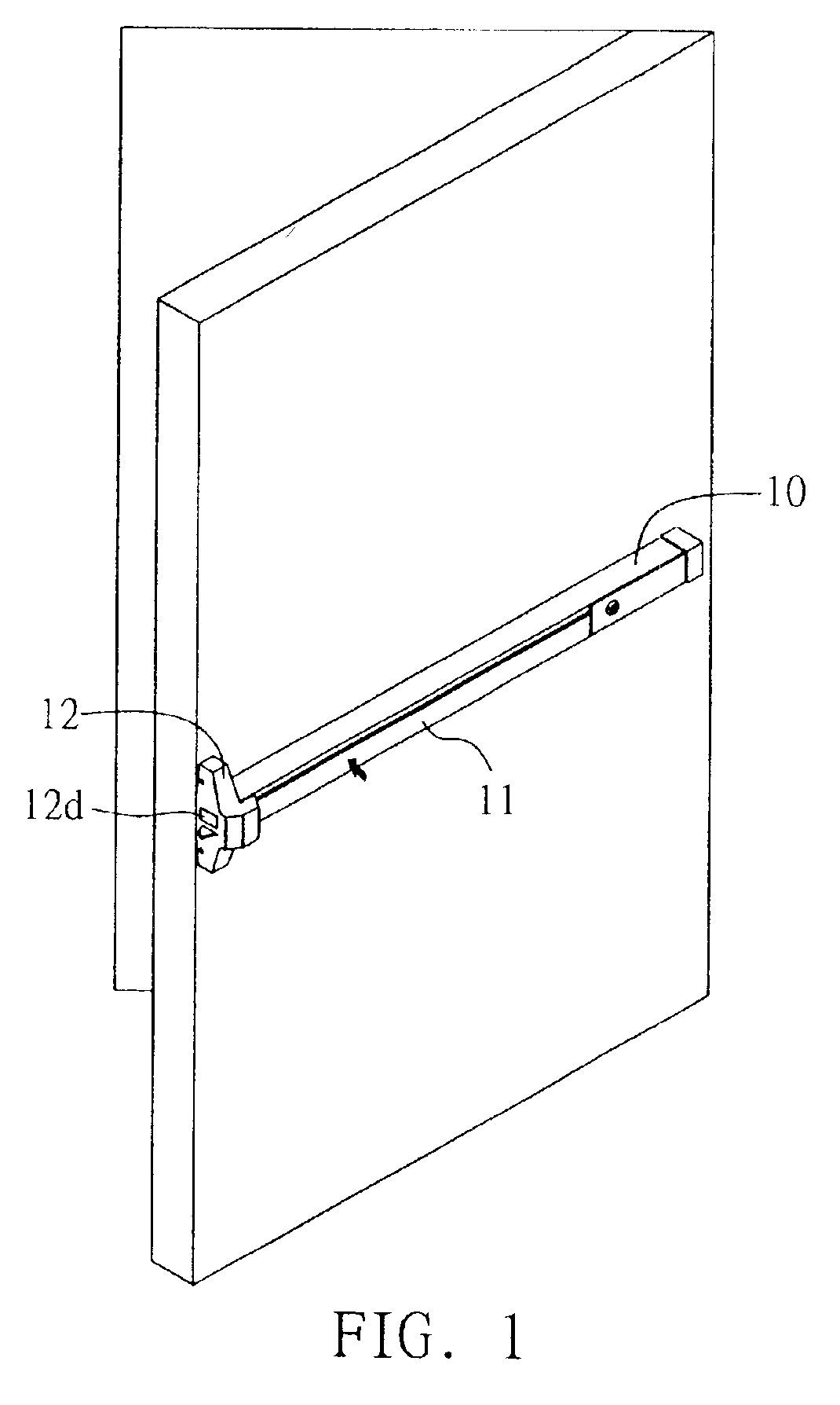
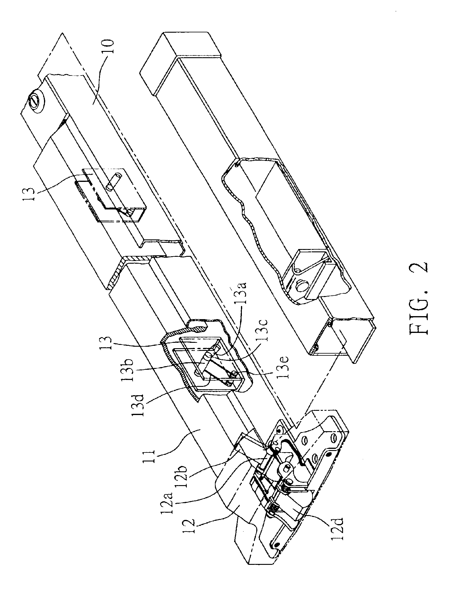
FIELD OF THE INVENTIONThe present invention relates to fire door lock mechanisms, and more particularly, to a fire door lock mechanism having a handlebar which can be vertically operated with respect to a fire door mounted with the fire door lock mechanism to thereby drive a lock bolt to open the fire door.BACKGROUND OF THE INVENTIONA conventional fire door, as shown in FIG. 1, is opened by depressing a handlebar 11 of a handlebar mount 10 horizontally located in the middle of the fire door, whereby a lock bolt 12d in a lock body 12 is retracted and relieves a locked state that closes and locks the fire door, thereby making the fire door opened. This operation is achieved by a diagonal depression motion of the handlebar 11 which is depressed by a user to move in a downward and diagonal direction. Please refer to FIGS. 2 and 3 which shown the structure of a conventional fire door lock being rotated by 90 degrees to be oriented in a horizontal direction for clear illustration. The han...

Claims


Application Information

Patent Timeline
Patent Type & Authority Patents(United States)
IPC IPC(8): E05B65/10
CPCE05B65/104Y10S292/65E05B65/1053Y10T292/0908Y10T292/0909
Inventor LIN, CHING-TIEN
Owner LIN CHING TIEN
Learn More