Precious stone setting

a technology of precious stones and setting, applied in the field of precious stone setting, can solve the problems of not being able to see and/or appreciate the aesthetic appearance of precious stones

Inactive Publication Date: 2005-02-22
CHENG YUAN I
View PDF13 Cites 27 Cited by
  • Summary
  • Abstract
  • Description
  • Claims
  • Application Information

AI Technical Summary

Benefits of technology

Accordingly, it is an object of the present invention to provide a precious stone setting comprises a shank body, a collet and an external rim. The circumferential edge of the shank body is provided with an inwardly recessed contracting cavity and the inner wall of the recessed cavity is provided with a groove. The precious stone is positioned at the collet having two pivotal shafts protruded into shaft holes preset at the inner side of the external rim to form a rotatable connection. The external side of the external rim, between two shaft holes, has two perpendicularly extended pivotal shafts and insertable into the groove of the shank body. The precious stone is free to pivotally rotate in accordance with the position of the external rin, the branch shafts of the collet in combination of the rotating of the external rim within the groove the precious stone is provided with sloping swinging angle and direction accordingly to the movement of the shank so as to provide an aesthetic appearance.
Still another object of the present invention is to provide a precious stone setting, wherein when the center of gravity of the precious stone changes, glittering effect is obtained and a pleasant visual effect is achieved.

Problems solved by technology

The conventional precious stone setting structure is always has a fixed position and if the shank is moved or rotated, the aesthetic appearance of the precious stone may not be seen and / or appreciated due to the change of the sloping of the reflective surface.

Method used


Image

  • Precious stone setting
  • Precious stone setting
  • Precious stone setting

Examples


Embodiment Construction

The following descriptions are of exemplary embodiments only, and are not intended to limit the scope, applicability or configuration of the invention in any way. Rather, the following description provides a convenient illustration for implementing exemplary embodiments of the invention. Various changes to the described embodiments may be made in the function and arrangement of the elements described without departing from the scope of the invention as set forth in the appended claims.

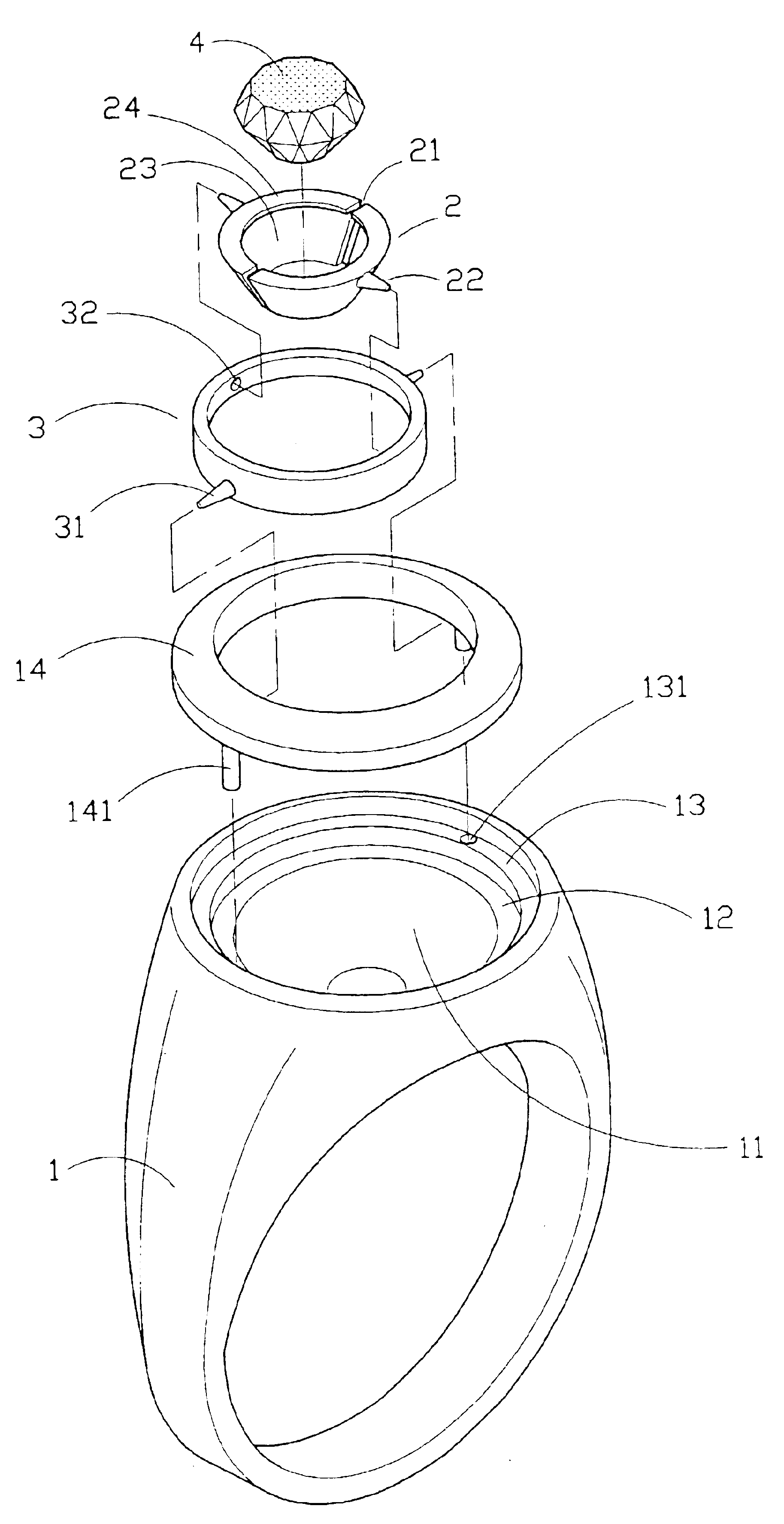
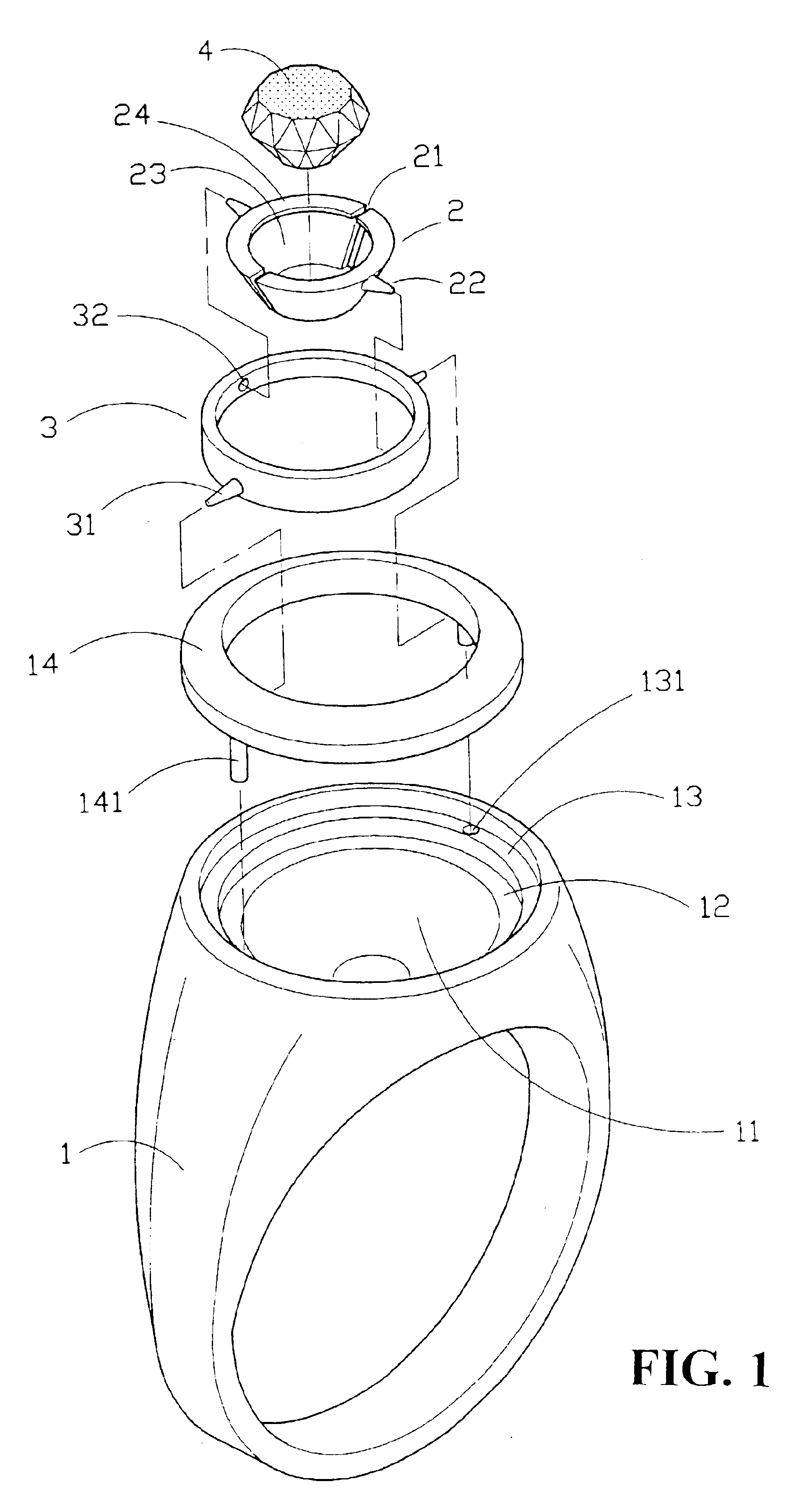
FIG. 1 is a perspective exploded view of the present invention. As can be seen from the figure, the precious stone setting comprises a shank 1, a collet 2 and an external rim 3. The circumferential edge of the shank 1 is a recessed cavity 11 having an inner circumferential edge mounted externally in sequence a stepped first recessed edge 12, a second recessed edge 13, and the bottom face of the second recessed edge 13 is provided with a plurality of insertion holes 131 for the mounting of pegs 141 prov...


PUM


Abstract

A precious stone setting is disclosed. The setting comprises a shank body, a collect and an external rim. The circumferential edge of the shank body is provided with an inwardly contracting cavity and the inner wall of the recessed cavity is provided with a groove. The precious stone is positioned at the collet having two pivotal shafts protruded into shaft holes preset at the inner side of the external rim to form a rotatable connection. The external side of the external rim, between two shaft holes, has two perpendicularly extended pivot shafts and are insertable into the groove of the body. The precious stone is free to pivotally rotate in accordance with the position of the external rim, the branch shaft of the collet and in combination of the rotating of the external rim within the groove the precious stone is provided with sloping swinging angle and direction accordingly to the movement of the shank so as to provide aesthetic appearance.

Description

BACKGROUND OF THE INVENTION(a) Technical Field of the InventionThe present invention relates to precious stone setting, and in particular, a collet for precious stone having two protruded branch shafts to insert into shaft holes at the inner edge of an external rim, and the circumferential edge of the external rim, between two shaft holes, is protrudingly provided with a branch shaft for mounting into groove formed on the shank. The collet and the branch shafts of the external rim move in accordance with positions of the directions of the shank to provide different pivoting, and swinging angle, forming into variations of configuration.(b) Description of the Prior ArtConventional precious stone setting has a collet having a cavity to receive directly a precious stone. The circumferential edge of the opening of the cavity is provided with a plurality of corresponding prongs. The precious stone is positioned on the cavity and a plurality of prongs hold the circumferential edge of the p...

Claims


Application Information

Patent Timeline
Patent Type & Authority Patents(United States)
IPC IPC(8): A44C17/00A44C17/02A44C9/00
CPCA44C17/0275A44C9/00
Inventor CHENG, YUAN-I
Owner CHENG YUAN I
Why Eureka
Try Eureka