Showerhead with grooved water release ducts

a showerhead and water release technology, applied in the field of showerheads, can solve the problems of wasting a great deal of fresh water, unable to produce an effective stream of water, and the showerheads tend to consume a substantial amount of fresh water, so as to achieve efficient and effective showering water and conserve water

Inactive Publication Date: 2006-05-23
CLARK
View PDF9 Cites 113 Cited by
  • Summary
  • Abstract
  • Description
  • Claims
  • Application Information

AI Technical Summary

Benefits of technology

[0004]A showerhead according to the present invention produces an efficient and effective shower of water in a manner that conserves water. In contrast to many prior art designs, the showerhead distributes water over a relatively wide area without relying on wasteful free flow water pressure obtained directly from the supply plumbing.

Problems solved by technology

Such systems tend to consume a substantial amount of fresh water, most of which is wasted.
Furthermore, most known showerheads produce a relatively narrow shower of water rather than distributing the water over a wide area.
Such narrowly focused showerheads do not produce an effective stream of water that efficiently provides a wide area of water coverage to the person taking the shower.
Such showerheads are not designed to provide pleasant visual effects to the user during use.

Method used


Image

  • Showerhead with grooved water release ducts
  • Showerhead with grooved water release ducts
  • Showerhead with grooved water release ducts

Examples


Embodiment Construction

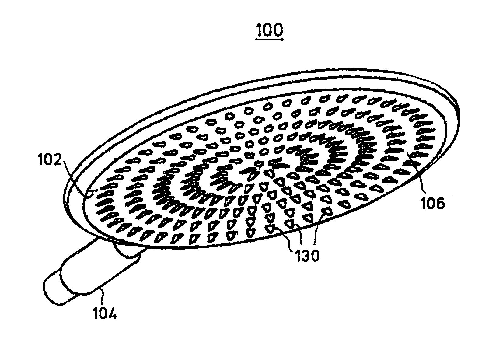
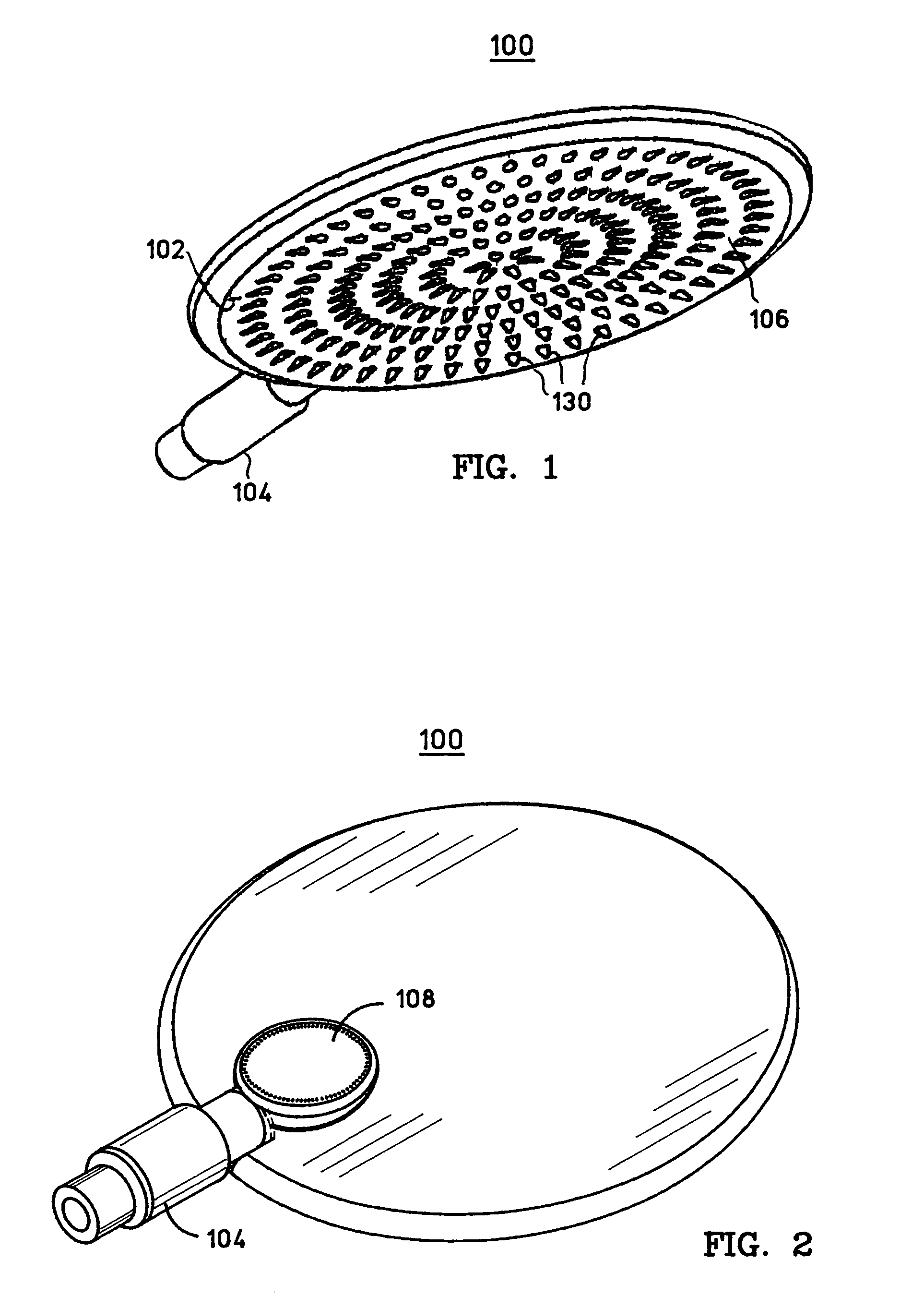
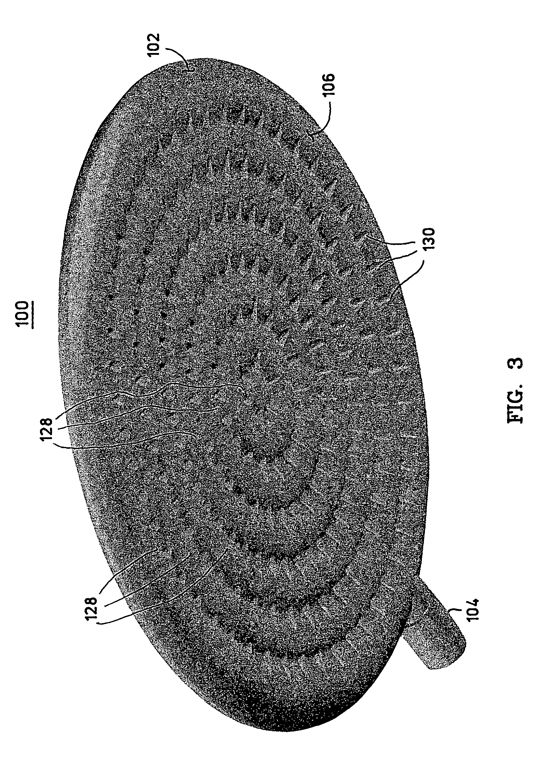
[0030]FIG. 1 is a perspective view of one side of a showerhead 100, and FIG. 2 is a perspective view of the other side of the showerhead 100. FIG. 1 shows the water distribution side of the showerhead 100, while FIG. 2 shows the water spray nozzle side of the showerhead 100. FIG. 3 is a three-dimensional perspective rendition of the water distribution side of the showerhead 100, showing the contoured / textured water distribution surface 102 of the showerhead 100.

[0031]In typical installations, the showerhead 100 is attached to a plumbing feature, e.g., a water pipe, that protrudes from a wall. Of course, the showerhead 100 may be installed in any number of alternate mounting configurations. The showerhead 100 may be connected to the water pipe via a suitable conduit, which may include one or more interconnected pipes, hoses, or the like. The showerhead 100 may include a suitably configured mounting element 104, e.g., a swivel joint, a telescoping joint, a ball joint, or a rotating jo...


PUM


Abstract

A showerhead as described herein includes a translucent hollow body having a fluid chamber, and a fluid distribution element configured to release fluid contained in the fluid chamber. The fluid distribution element includes a plurality of raised concentric rings having peaks that serve as the fluid release points. The fluid distribution element contains a number of fluid ducts that are specifically shaped to transport the fluid from the fluid chamber toward the fluid release points. The translucent nature of the showerhead creates an optical lens effect that illuminates the showerhead and the water droplets formed by the showerhead. The illumination of the water droplets creates a pleasant showering experience for the user.

Description

RELATED APPLICATION[0001]The subject matter disclosed herein is related to the subject matter contained in U.S. patent application Ser. No. 10 / 443,300, titled SHOWERHEAD WITH OPTICAL LENS FEATURE.FIELD OF THE INVENTION[0002]The present invention relates generally to shower fixtures. More particularly, the present invention relates to a showerhead.BACKGROUND OF THE INVENTION[0003]The prior art is replete with showerhead designs. Conventional showerheads utilize unmodified free flow water pressure to generate a spray of water. Water exiting a traditional showerhead is sent in a single direction by the force of the water pressure created in the supply plumbing. Such systems tend to consume a substantial amount of fresh water, most of which is wasted. Furthermore, most known showerheads produce a relatively narrow shower of water rather than distributing the water over a wide area. Such narrowly focused showerheads do not produce an effective stream of water that efficiently provides a ...

Claims


Application Information

Patent Timeline
Patent Type & Authority Patents(United States)
IPC IPC(8): A62C2/08B05B1/14E03D9/03B05B1/16B05B1/18
CPCB05B1/185B05B1/1645Y10T137/3112
Inventor CLARK, FRANK
Owner CLARK
Why Eureka
Try Eureka