Clamp device

Inactive Publication Date: 2005-03-01
BLACK & DECKER INC
View PDF42 Cites 132 Cited by
  • Summary
  • Abstract
  • Description
  • Claims
  • Application Information

AI Technical Summary

Problems solved by technology

The problem with these devices is that they operate in a linear fashion, with the clamping jaws sliding directly toward and away from one another.
This structure presents some limitations such as limiting access of the clamp in tight spots, etc.
T

Method used


Image

  • Clamp device
  • Clamp device
  • Clamp device

Examples


Embodiment Construction

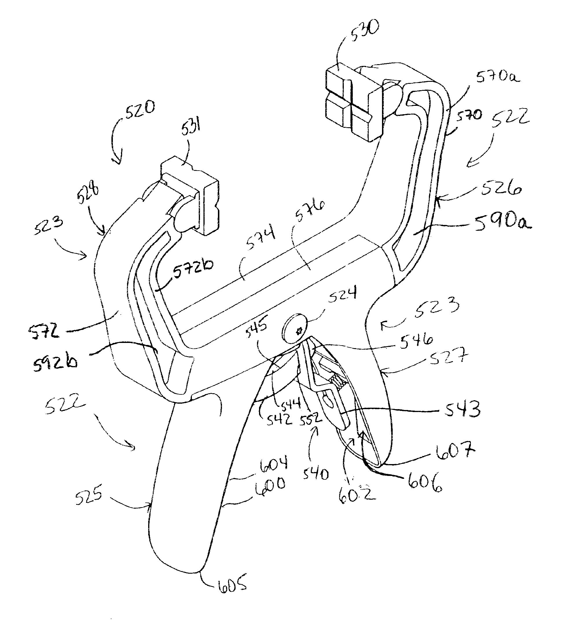
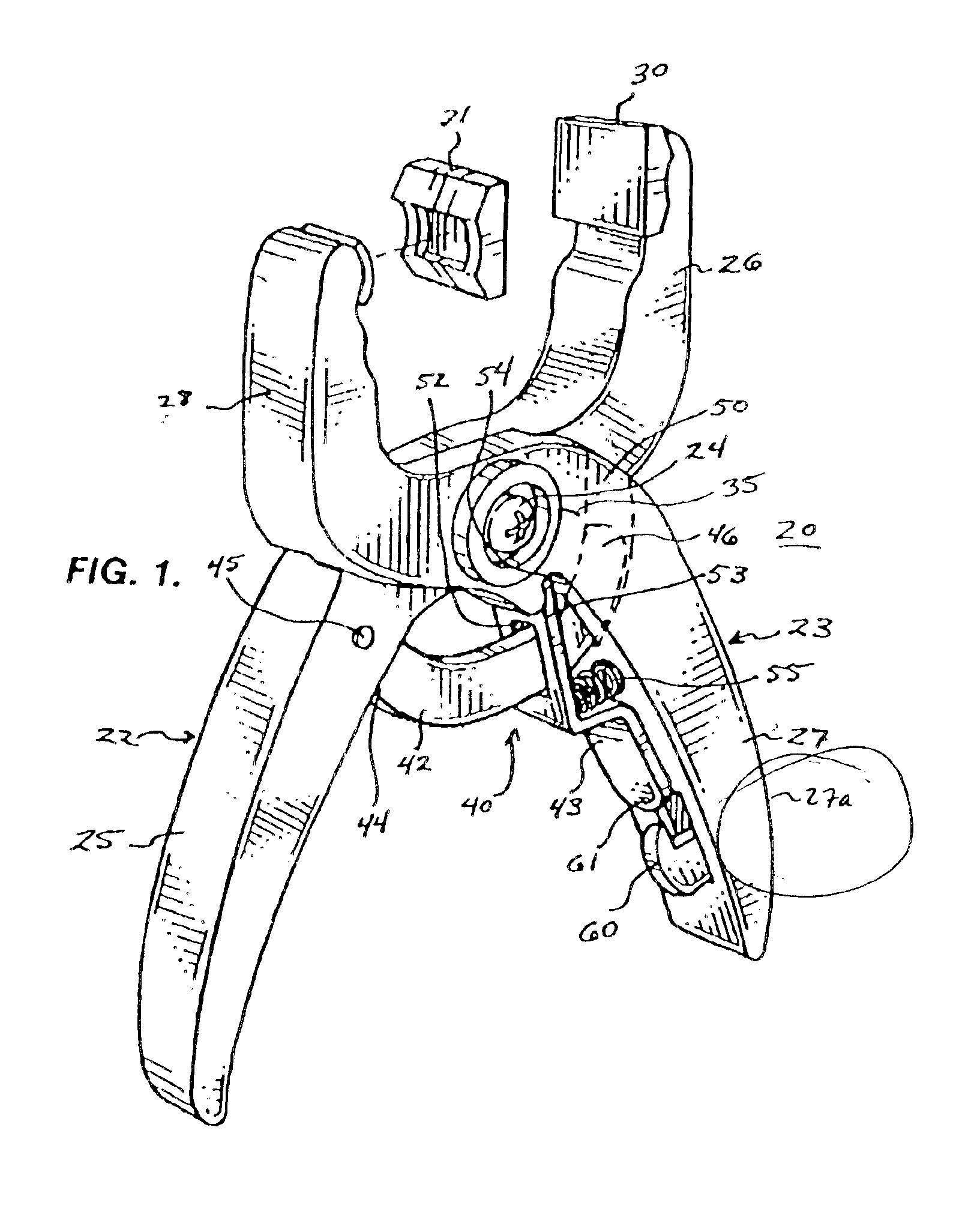
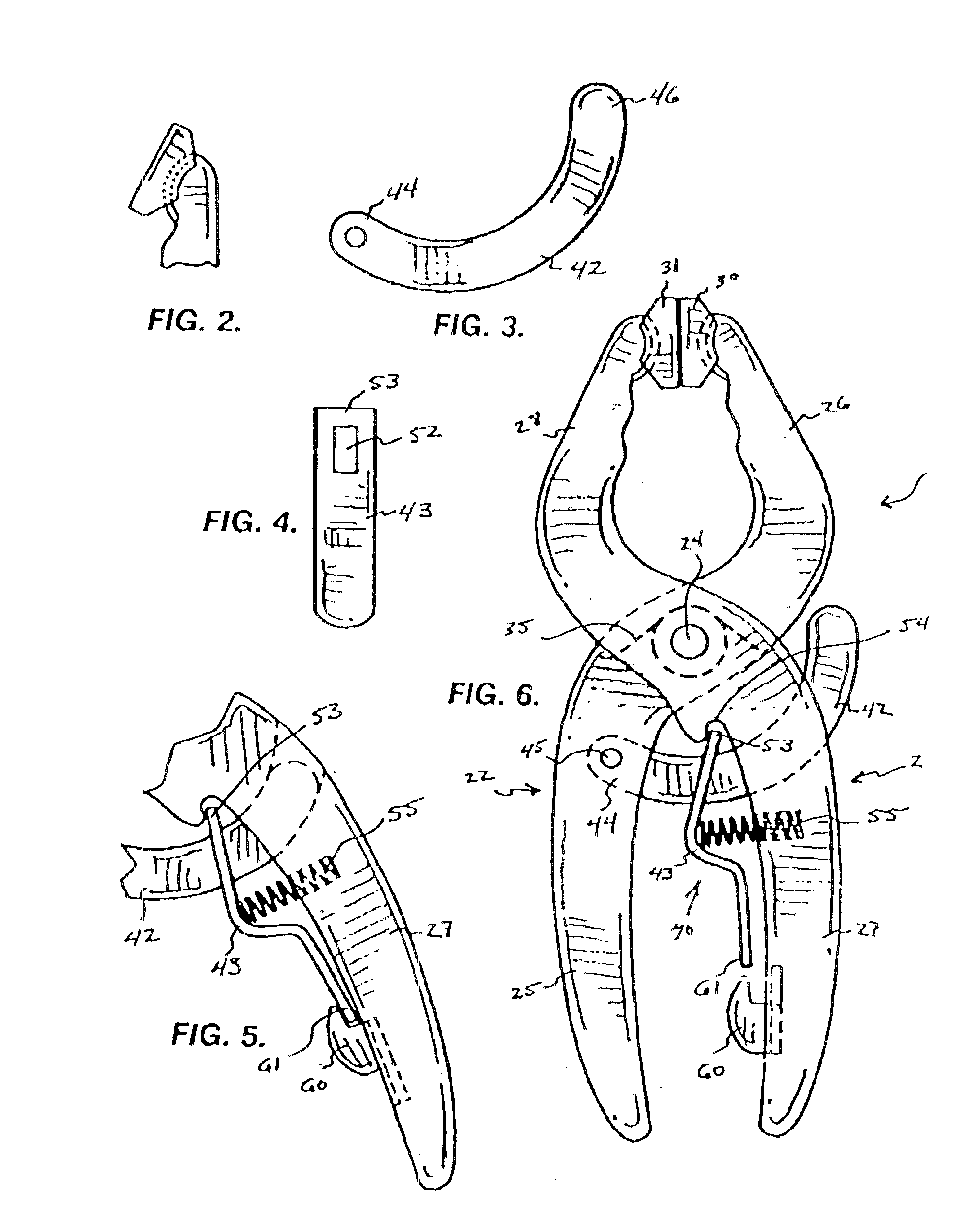
Turning now to the drawings in which like reference characters indicate corresponding elements throughout the several views, attention is first directed to FIG. 1, which illustrates a clamp device generally designated 20. Clamp device 20 includes a pair of members 22, 23 pivotally connected by a pivot 24 (bolt, rivet, screw, etc.) for pivotal opposed operation (i.e. scissors like motion). Member 22 includes a handle portion 25 and a jaw portion 26. Similarly, member 23 includes a handle portion 27 and a jaw portion 28. The distal end of jaw portion 26 has a snap-fit gripping member 30 pivotally coupled thereto (see FIG. 2 for pivotal action). The distal end of jaw portion 28 has a snap-fit gripping member 31 pivotally coupled thereto (illustrated in an unsnapped position for clarity). Included in this embodiment is an optional spring 35 which is carried by pivot 24 with outwardly extending ends which engage handle portions 25, 27 to bias clamp device 20 into the open position illust...


PUM


Abstract

A clamp device is disclosed having a first member having a handle portion and a jaw portion. A second member has a handle portion and a jaw portion. The handle portion and jaw portion of the second member define a notch extending from an inner surface of the handle portion of the second member at least partially into the jaw portion of the second member, the second member being formed as a single piece. A pivot is pivotally coupling the first member and the second member intermediate their respective handle portion and jaw portion for opposed pivotal motion. An arcuate clamp bar has a first end coupled to the first member and a second end, an arc of the arcuate clamp bar being concentric with the pivot. A brake lever has an end pivotally coupled to the second member at the notch. The end contacts the jaw portion of the second member. The brake lever has an aperture with the arcuate clamp bar extending therethrough. The brake lever is movable laterally between a frictionally engaged position, frictionally engaging the arcuate clamp bar and a disengaged position.

Description

BACKGROUND OF THE INVENTIONThis invention relates generally to clamping devices, and more particularly to clamping devices which can be manipulated with one hand.Clamping devices are well known and have been in use for many years. Particularly, straight bar friction locking clamps are extremely popular. These clamp devices can be operated one handed, and are very effective. The problem with these devices is that they operate in a linear fashion, with the clamping jaws sliding directly toward and away from one another. This structure presents some limitations such as limiting access of the clamp in tight spots, etc.Often, pliers are used to clamp items together because the motion of the handles permits their use in closer spaces. The problem with pliers is that the user must maintain the pressure on the handles, as they do not remain locked in position. Locking pliers using friction locks have been introduced, but while they will lock into a specific configuration, they will not clam...

Claims


Application Information

Patent Timeline
IPC IPC(8): B25B7/18B25B7/04B25B7/14B25B7/00
CPCB25B5/06B25B7/18B25B7/14B25B7/04
Inventor HOPPER, RYAN K.SEDLACEK, WALTER J.POOLE, DANIEL L.POOLE, ROBERT N.
Owner BLACK & DECKER INC
Why Eureka
Try Eureka