Support base for equipment

a technology for supporting bases and equipment, applied in the direction of machine supports, scaffold accessories, snow traps, etc., can solve the problems of deterioration of mechanical attachments such as nailing blocks to roofs, damage to roofs, and expensive roof repairs

Inactive Publication Date: 2005-03-08
VALENTZ FAMILY PARTNERSHIP
View PDF49 Cites 49 Cited by
  • Summary
  • Abstract
  • Description
  • Claims
  • Application Information

AI Technical Summary

Problems solved by technology

Over a period of time, the movement of the blocks against a roof surface damage the roof.
This usually resulted in a leak and required expensive roof repair.
However, mechanical attachment such as nailing the block to the roof has been shown to deteriorate in a relatively short time period.
The blocks then break loose and a leak occurs at the attachment holes.
Invariably the seal between the roof and the post will fail resulting in a leak.
As discussed above, holes lead to leaks, a definite disadvantage of fixed base...

Method used


Image

  • Support base for equipment
  • Support base for equipment
  • Support base for equipment

Examples


Embodiment Construction

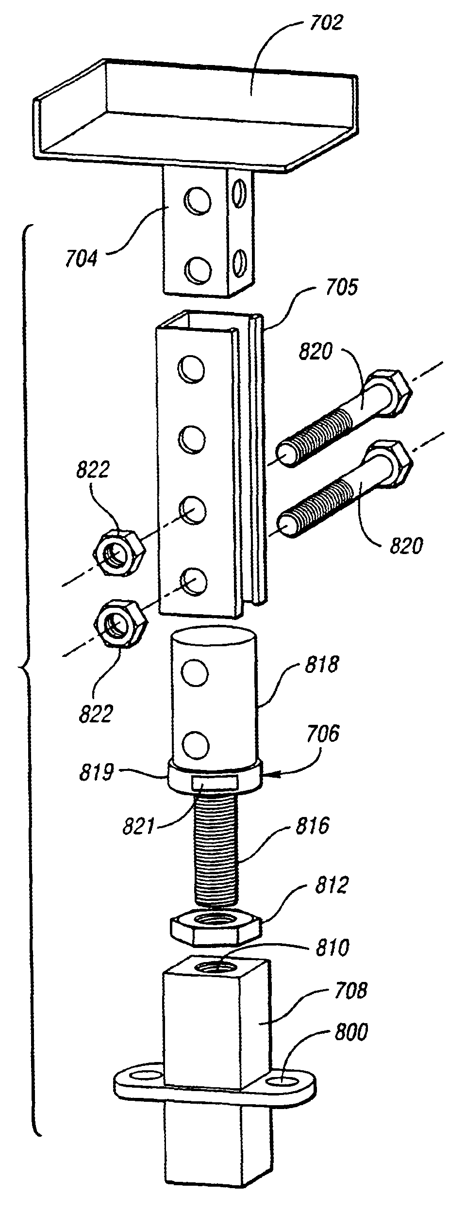
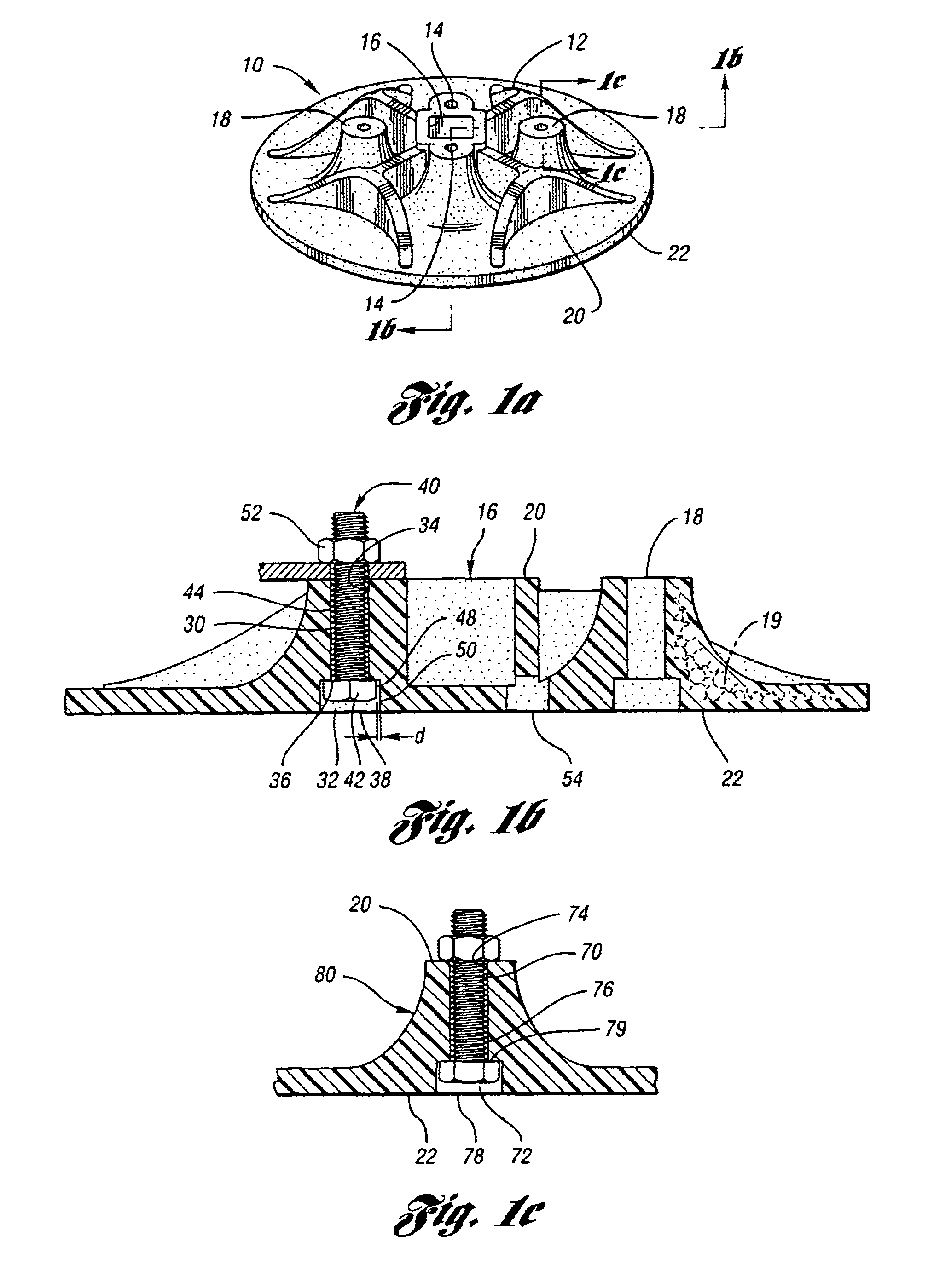
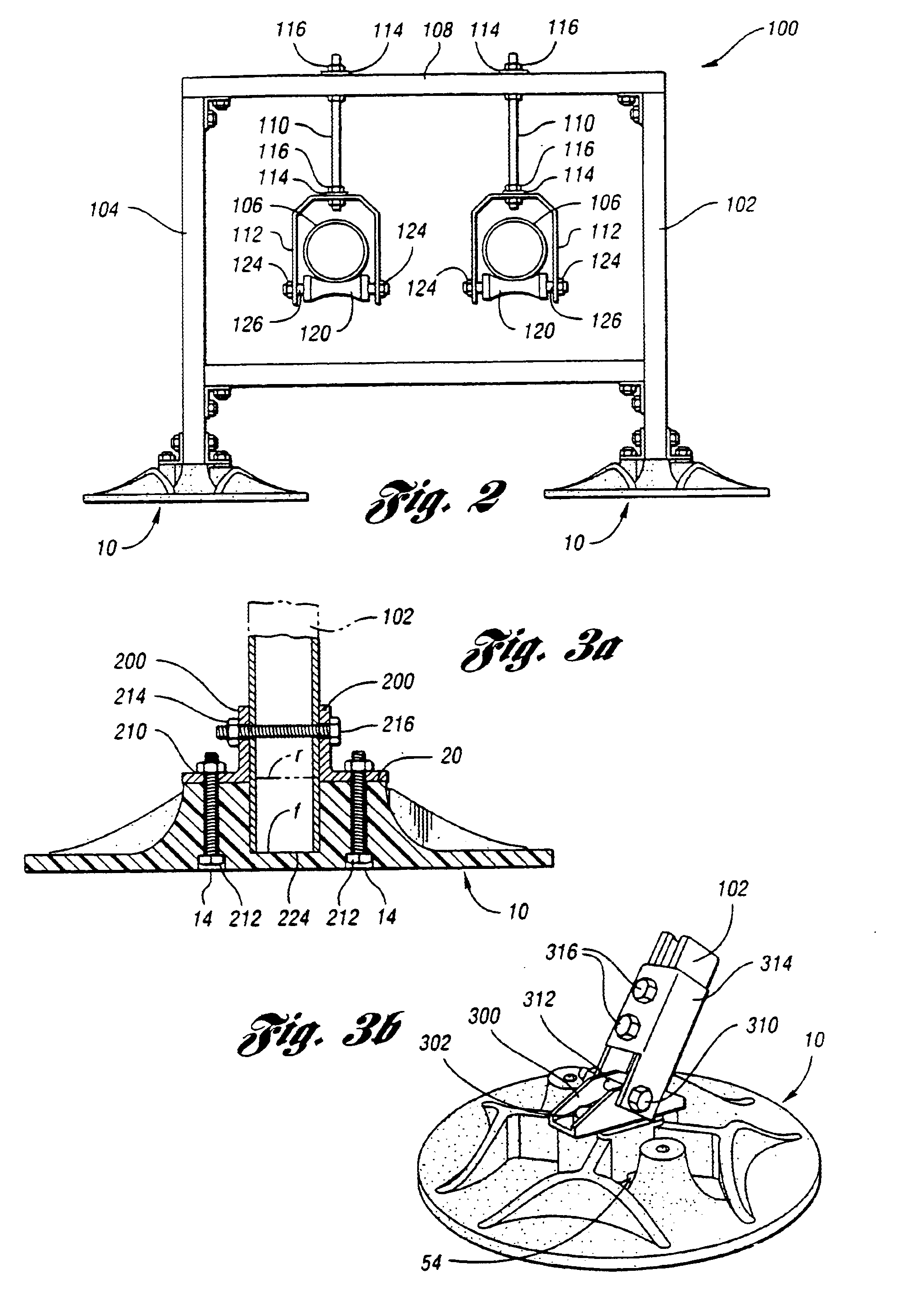
With reference to FIG. 1a, there is shown a support base 10 for supporting a load and dispersing the load over a surface contact area. Generally, support base 10 has a network of ridges 12 which extend radially outward from a central cavity 16. Radially extending ridges 12 serve to stiffen the support base 10 and prevent it from fracturing when a concentrated load is applied. Support base 10 further includes a plurality of inner apertures 14. Inner apertures 14 are located generally adjacent to the inner cavity 16 and are configured to receive various load interfacing bracketry for interfacing the load with a support base 10. The specific configurations of the inner apertures 14 will be described hereinafter. Additionally, support base 10 has outer apertures 18 which are disposed radially outward of inner cavity 16. As with inner apertures 14, outer apertures 18 are configured to receive interfacing bracketry which interface the load with support base 10. Accordingly, the configurat...


PUM


Abstract

A support base for distributing a concentrated load over a contact surface is disclosed. The support base includes a body formed of moldable polymeric material having a top surface and a generally planar bottom surface. At least one recess is integrally formed in the top surface for receiving a support member. The support member transfers the concentrated load to the planar body. Furthermore, at least one through bore is provided in the support base, and the through bore extends from the top surface to the bottom surface of the support base for receiving a fastener. The through bore has a shaft portion and a relatively oversized cavity portion adjacent to the bottom surface for receiving fasteners such as nuts for securing bolts, as well as, bolt heads of different sizes and configurations. The support base has many advantages over the prior art for example, the base may be attached to different interface bracketry without be modified.

Description

TECHNICAL FIELDThe present invention relates to systems for supporting and hanging pipes and other loads on rooftops.BACKGROUND ARTIt is common in a commercial industrial environment to have various operating pipes, conduits, and other equipment positioned on and extending along the ground or over the tops of roofs. For example, these pipes and conduits may be connected to an air conditioning unit positioned on a building roof.Frequently the pipes carry fluids which have operating temperatures fluctuating over a wide range. As the temperature of the fluids carried by the pipes changes the pipes will expand or contract accordingly. Typically, the pipes may expand and contract greatly. Therefore, the support for these pipes as they run over the ground and / or over a roof must sustain the pipe load but also must be sufficiently flexible to withstand the expansion and contraction caused by fluctuations in operating parameters and the prevailing weather.On a building roof it was common pr...

Claims


Application Information

Patent Timeline
IPC IPC(8): E04G1/24E04G1/00E04G5/00E04G5/02E04D13/12
CPCE04D13/12E04G5/02E04G5/00E04G1/24
Inventor VALENTZ, ARTHUR J.NEMAZI, JOHN E.
Owner VALENTZ FAMILY PARTNERSHIP
Why Eureka
Try Eureka