Location adjusted HVAC control

a technology of hvac control and location adjustment, which is applied in the direction of instruments, heating types, and static/dynamic balance measurement, etc., can solve the problem that the above control may not fully reflect the appropriate level of heating demand

Inactive Publication Date: 2005-03-08
CARRIER CORP
View PDF11 Cites 109 Cited by
  • Summary
  • Abstract
  • Description
  • Claims
  • Application Information

AI Technical Summary

Benefits of technology

In a preferred embodiment, the information received by the computer includes individual selections of comfort entered into data entry devices at the various locations. Each data entry device is operative to store selected comfort levels and timely provide the stored results to the network computer.

Problems solved by technology

The above control may not completely reflect the appropriate levels of demand for heating or cooling at one or more of the locations.

Method used


Image

  • Location adjusted HVAC control
  • Location adjusted HVAC control
  • Location adjusted HVAC control

Examples


Embodiment Construction

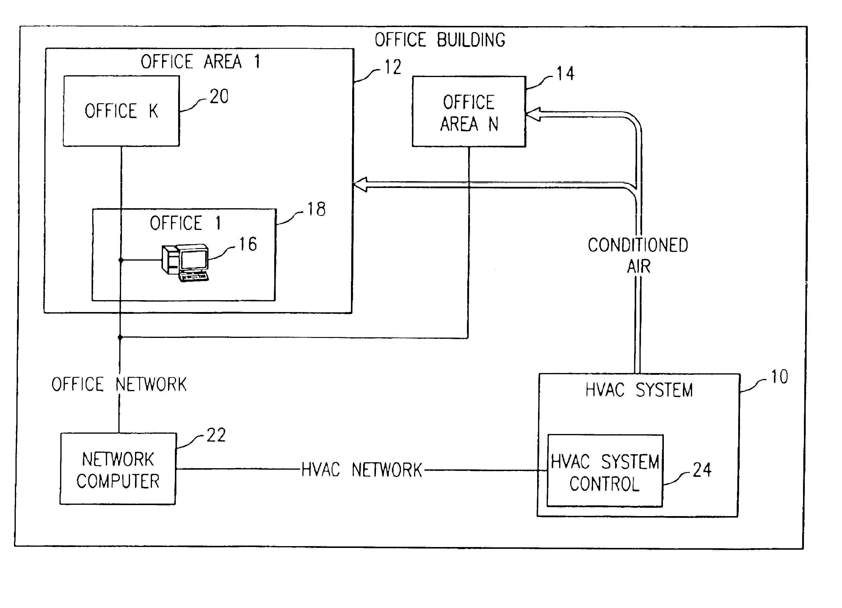
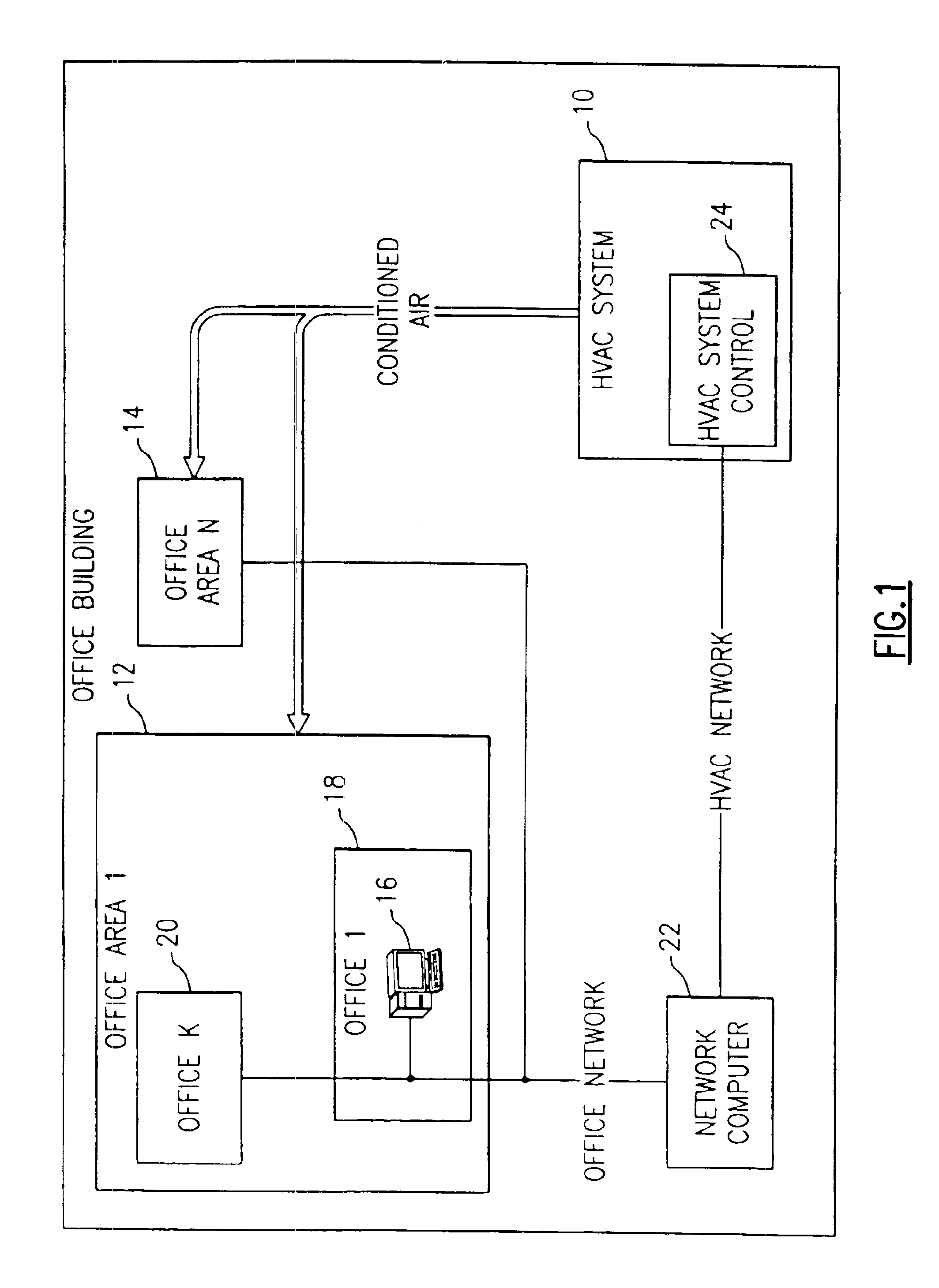
Referring to FIG. 1, an HVAC system 10 provides conditioned air to a number of individual office area locations such as office area location 12 and office area location 14. Each office area location will carry a particular office area index value for purposes of identifying comfort level data originating from the particular office area location. This is indicated by office area location 12 being office area 1 whereas office area location 14 is identified as office area N.

Each office area location is seen to include a number of individual personal computers such as computer 16 located in an office 18. Each office within office area location 12 is identified by an office index “K” where K=for instance 1 for office 18 and is for instance another value for office 20.

Each computer within an office in a particular office area location is preferably connected to a network computer 22. As will be explained in detail hereinafter, the network computer 22 is operative to collect comfort level ...


PUM


Abstract

A system and method allows occupants in various locations to provide indications as to their respective levels of comfort. The indications as to comfort level are provided to a network computer. The network computer is operative to compute overall levels of comfort for each location by using a weighting factor for that location in combination with the indications as to levels of comfort These overall levels of comfort are sent to an HVAC control for further analysis prior to controlling the HVAC system that is to provide conditioned air to the locations. The resulting control of the HVAC system is influenced by the over weighting or under weighting factors used in computing the comfort levels for the locations.

Description

BACKGROUND OF THE INVENTIONThis invention relates to the control of an HVAC system using information gathered from locations to be provided with conditioned air from the HVAC system.The control of an HVAC system has heretofore depended on gathering information such as sensed temperature from the locations in which conditioned air is to be provided by the system. The temperatures are usually sensed by temperature sensors in these locations. The sensed temperatures are usually compared with arbitrarily defined set point temperatures for the locations. The difference in these temperatures is used to define the demand for heating or cooling at each location. These location specific demands are used to control one or more HVAC systems providing conditioned air to the locations.The above control may not completely reflect the appropriate levels of demand for heating or cooling at one or more of the locations. In this regard, some locations may have certain unique demands for heating or co...

Claims


Application Information

Patent Timeline
Patent Type & Authority Patents(United States)
IPC IPC(8): F24F11/00G05D23/19G05D27/00G05D27/02
CPCF24F11/006G05D27/02G05D23/1902F24F2011/0057F24F2011/0064F24F11/30F24F2120/20F24F11/62F24F11/65
Inventor DUDLEY, KEVIN F.
Owner CARRIER CORP
Why Eureka
Try Eureka