Supination/pronation therapy device

a technology of pronation and supination, which is applied in the field of orthopaedic devices, can solve the problems of patient loss of rotational flexibility, uneven force across the device, and no one promotes rotation or creates rotational forces,

Inactive Publication Date: 2005-03-15
R & R HLDG
View PDF30 Cites 32 Cited by
  • Summary
  • Abstract
  • Description
  • Claims
  • Application Information

AI Technical Summary

Problems solved by technology

Those forces may be uneven across the device.
Another problem with existing devices is that none promote rotation or create rotational forces.
Whether there is a reduction in the range of supination or pronation, a patient can lose that flexibility of rotation.
Typically, any rotational therapy is effectively limited to a therapist's office or similar rehabilitation facility.

Method used


Image

  • Supination/pronation therapy device
  • Supination/pronation therapy device
  • Supination/pronation therapy device

Examples


Embodiment Construction

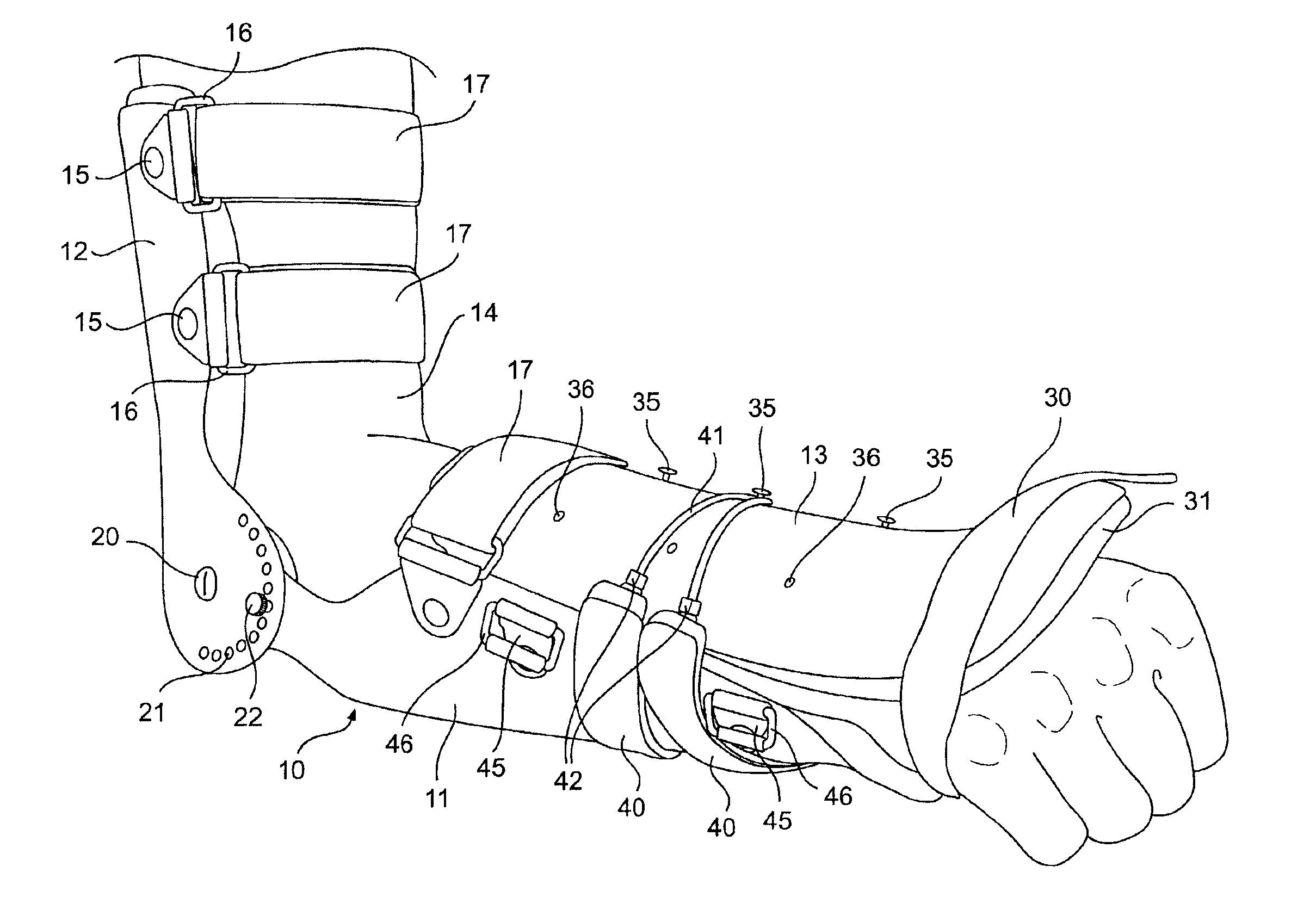
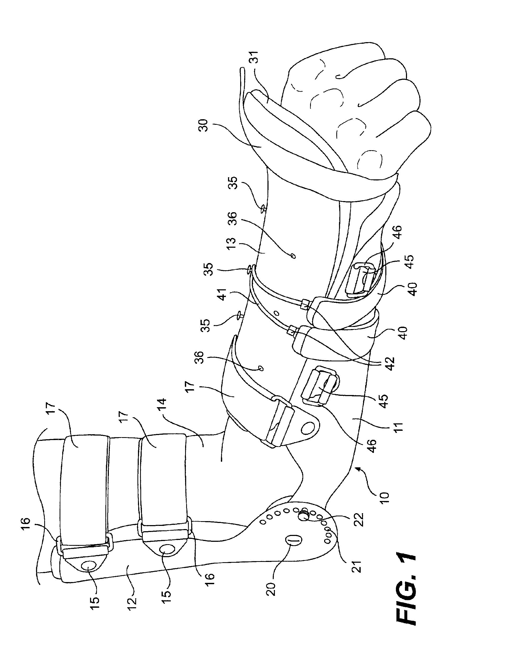
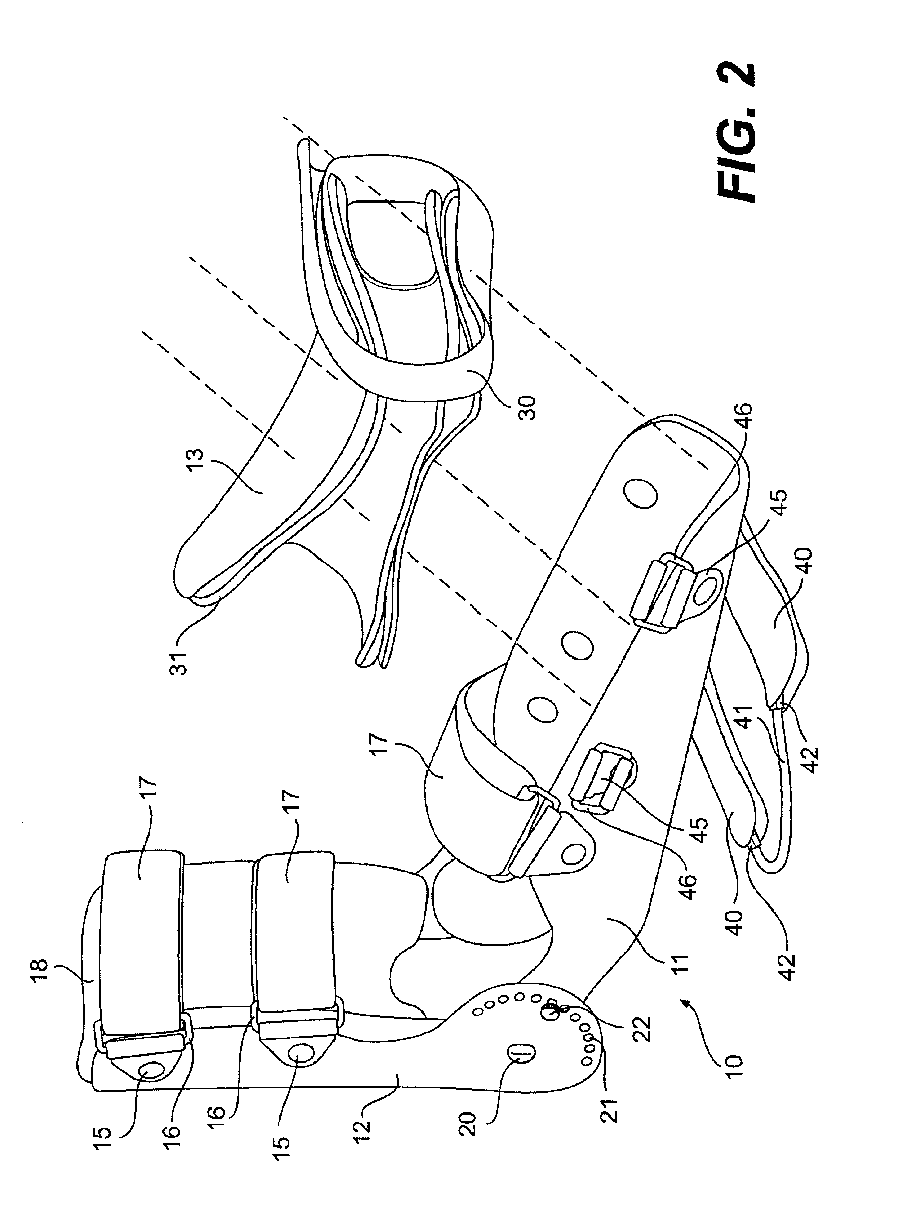
The present invention is directed to an orthotic device used to promote the rotation of a patient's wrist and forearm. The rotation of the wrist in the direction in which the palm is pointed upwardly or skywardly is called supination. The rotation of the wrist in which the palm is facing downwardly is referred to as pronation. The orthotic device described herein can apply either a dynamic or static force in the rotational direction of supination or pronation. Further, that rotational force may be varied by a user or therapist in accordance with the needs of a patient.

Turning now to the drawings, FIGS. 1,2 and 4 illustrate an orthotic device in accordance with the present invention in which a dynamic force of rotation can be applied to a patient's forearm. (There is reference made throughout of a patient's “wrist” or “forearm” when referring to the application of therapy herein. The terms are effectively referenced to interchangeably.) The orthotic device 10 is a brace adapted to su...


PUM


Abstract

An orthotic device promotes both supination and pronation of a patient's wrist. A forearm enclosure is adapted to substantially wrap around a forearm. A forearm support member is adapted to slidably receive the forearm enclosure wherein the support member wraps partially around the forearm enclosure. A post is mountable on the forearm enclosure. An anchor is mounted on the support member. A tensioning member is connected to the anchor and on the other end to the post, wherein a rotational force of supination or pronation will be created on the forearm enclosure depending on the direction which the tensioning members extend from the anchor to the post.

Description

The present invention relates to an orthotic device that promotes supination and pronation of a patient's wrist. A combination of components of the device allows it to apply either dynamic or static rotational forces to a joint in need of therapy. The force generated by the components and their direction can be quantified and used in therapeutic treatment.BACKGROUND OF THE INVENTIONThere are many known orthotic devices including those specifically directed to rehabilitation of various joints such as elbows and wrists. Typically, these apparatuses are static or have a single pressure / force that is applied during operation. Those forces may be uneven across the device.Another problem with existing devices is that none promote rotation or create rotational forces. It is common in wrist or arm injuries to have some temporary or permanent lose of rotation in the forearm / wrist, for instance when an arm is immobilized in a cast for an extended period of time. Whether there is a reduction i...

Claims


Application Information

Patent Timeline
Patent Type & Authority Patents(United States)
IPC IPC(8): A61F5/01
CPCA61F5/013
Inventor HOPKINS, RONALD B.SIELLER, RICHARD T.
Owner R & R HLDG
Why Eureka
Try Eureka