Motion compensated image-guided focused ultrasound therapy system

a focused ultrasound and image-guided technology, applied in the field of thermal treatment systems, can solve the problems of significant delays, one or both of these coordinate systems becoming mis-registered with the other coordinate systems, and significant inefficiencies in the treatment process

Active Publication Date: 2009-04-02
INSIGHTEC
View PDF98 Cites 168 Cited by
  • Summary
  • Abstract
  • Description
  • Claims
  • Application Information

AI Technical Summary

Problems solved by technology

If unplanned movement of either the transducer or the patient is detected, however, one or both of these coordinate systems become mis-registered with the other coordinate systems.
This introduces significant inefficiencies in the treatment process and may generate significant delays.
However, if the patient moves, the patient coordinate system in which the target tissue region is defined, will become mis-registered with the imaging and therapeutic coordinate systems.
However, electronic phasing changes or electrical impedance changes within the control circuitry of the transducer may still generate misalignment between the imaging and therapy beams; that is, cause mis-registration between the imaging and therapeutic coordinate systems.
In addition, immobilization of the target tissue region of the patient may not always be practically accomplished.
Since a large number of sonications may be required in order to fully treat the target tissue mass, the overall time required can be quite significant.
This means that the patient must remain motionless in the imaging device for a significant period of time, which can be very stressful.
Thus, the use of image-guided focused therapy systems are limited to treating tissue masses with small motion amplitudes or to those that are easily immobilized.
While this technique may be successful when tracking a target tissue mass that moves in accordance with a periodic cycle, it does not address non-periodic movement of the target tissue mass; for example, when the patient moves within the imaging device.

Method used


Image

  • Motion compensated image-guided focused ultrasound therapy system
  • Motion compensated image-guided focused ultrasound therapy system
  • Motion compensated image-guided focused ultrasound therapy system

Examples


Embodiment Construction

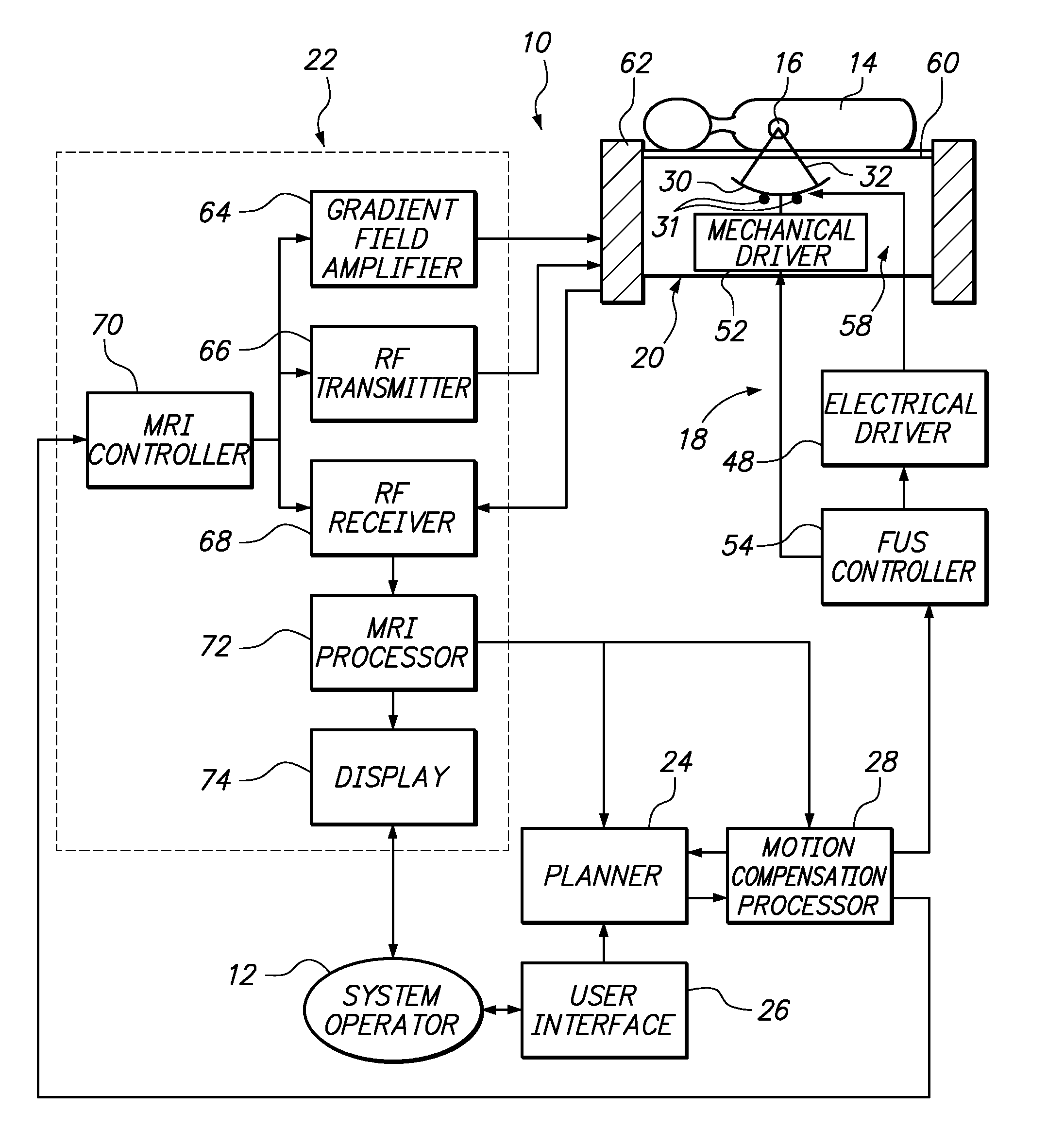
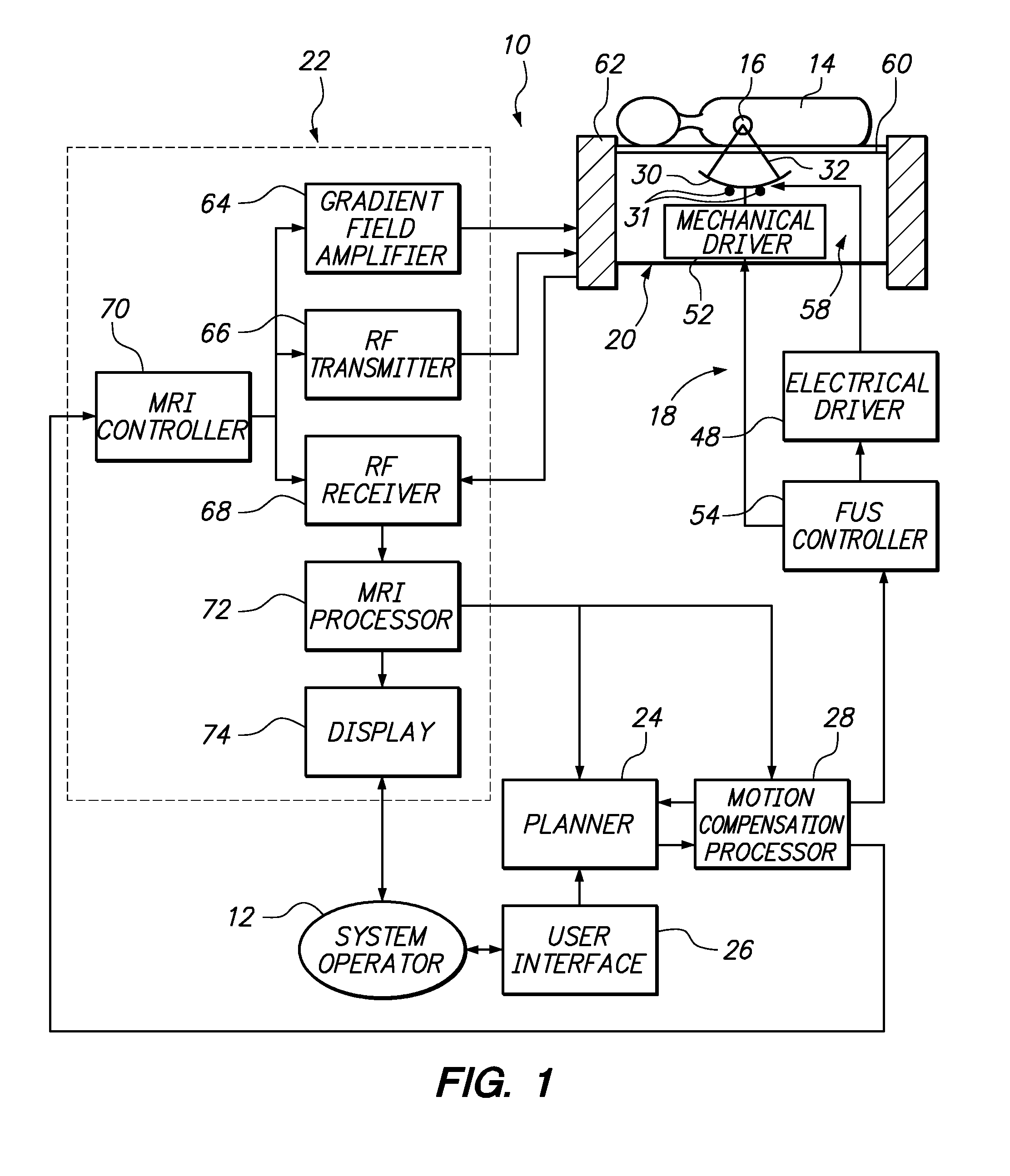
[0028]Referring generally to FIG. 1, an image-guided therapy system 10 arranged in accordance with one embodiment of the present inventions will now be described. The system 10 is designed to be operated by a system operator 12 to treat a target tissue mass 16 (e.g., a tumor) within an internal body region of a patient 14. The system 10 generally comprises a focused thermal treatment subsystem 18, a patient table 20, an imaging subsystem 22, a planner 24, a user interface 26, and a motion compensation processor 28. It should be noted that the elements illustrated in FIG. 1 are functional in nature, and are not meant to limit the structure that performs these functions in any manner. For example, several of the functional blocks can be embodied in a single device, or one of the functional blocks can be embodied in multiple devices. Also, the functions can be performed in hardware, software, or firmware.

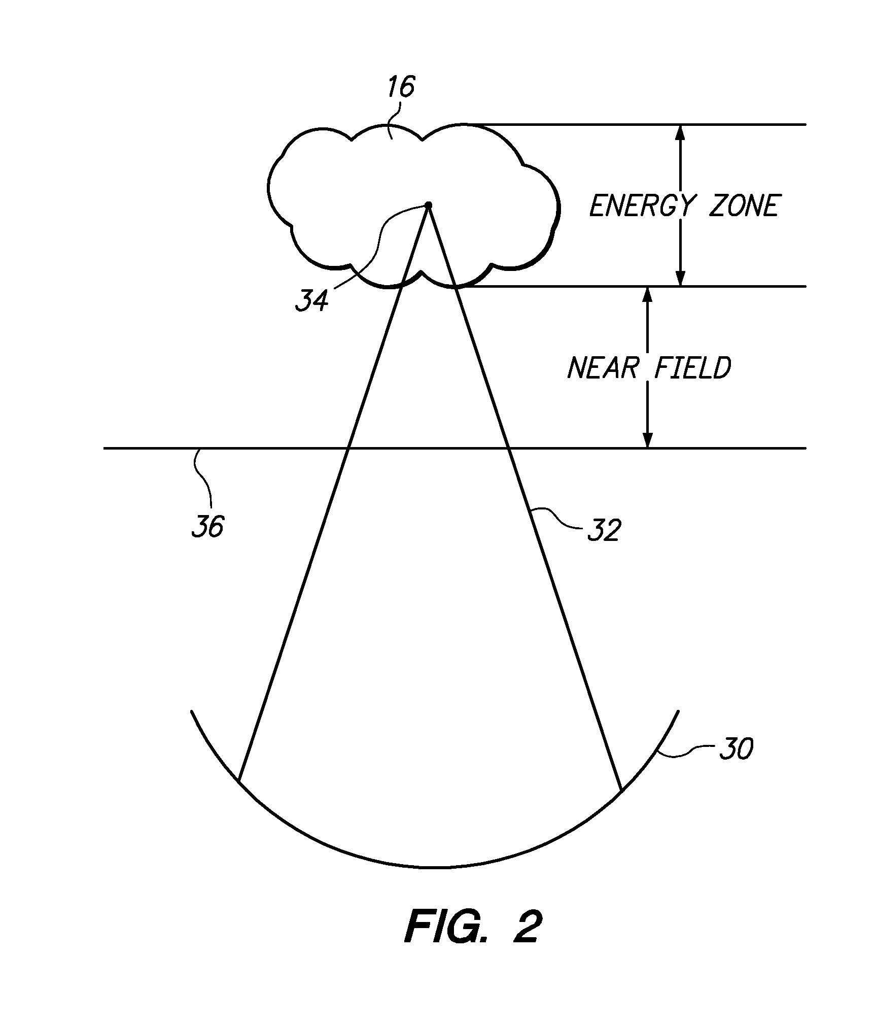
[0029]Referring further to FIG. 2, the thermal treatment system 12 comprises a the...


PUM


Abstract

An image-guide therapy system comprises a thermal treatment device (e.g., an ultrasound transducer) configured for transmitting a therapeutic energy beam, and The system further comprises an imaging device (e.g., a magnetic resonant imaging (MRI) device) configured for acquiring images of the target tissue mass and the thermal treatment device. The system further comprises a controller configured for controlling thermal dose properties of the thermal treatment device to focus the energy beam on a target tissue mass located in an internal body region of a patient, and a processor configured for tracking respective positions of the thermal treatment device and the target tissue mass in a common coordinate system based on the acquired images. The system may optionally comprise a display configured for displaying the acquired images.

Description

FIELD OF THE INVENTION[0001]The present invention relates to thermal treatment systems, and more particularly, to image-guided focused ultrasound therapy systems.BACKGROUND OF THE INVENTION[0002]Thermal energy, such as generated by high intensity focused ultrasound (acoustic waves with a frequency greater than about 20 KHz, and more typically between 50 KHz and 5 MHz), may be used to therapeutically treat internal tissue within a patient. For example, ultrasonic waves may be used to ablate tumors (e.g., breast tumors and uterine fibroids), thereby obviating the need for invasive surgery. For this purpose, a phased transducer array having transducer elements driven by electrical signals to produce ultrasonic energy can be placed external to the patient, but in close proximity to the target tissue mass to be ablated.[0003]The transducer is geometrically shaped and positioned, such that the ultrasonic energy is focused at a “focal zone” corresponding to the target tissue mass within th...

Claims


Application Information

Patent Timeline
Patent Type & Authority Applications(United States)
IPC IPC(8): A61B5/055A61N7/02
CPCA61B5/015A61B5/055A61B5/416A61B5/7207A61B8/0841A61B8/5276G01R33/4814A61B2017/00084A61B2017/00694A61B2019/5236A61B2019/5287A61N7/02G01R33/4804A61B19/5244A61B8/4245A61B2090/363A61B34/20A61B2090/374
Inventor VORTMAN, JACOBMEDAN, YOAVASSIF, BENNY
Owner INSIGHTEC
Why Eureka
Try Eureka