Method and apparatus for volumetric image navigation

a volumetric image and navigation technology, applied in applications, ultrasonic/sonic/infrasonic diagnostics, diagnostic recording/measuring, etc., can solve the problems of relatively rapid procedure, limited signal-to-noise ratio, and ultrasonic scanning

Inactive Publication Date: 2010-11-30
CICAS IP LLC
View PDF53 Cites 236 Cited by
  • Summary
  • Abstract
  • Description
  • Claims
  • Application Information

AI Technical Summary

Benefits of technology

[0018]In addition, for probes or instruments being used that are capable themselves of generating images, such as ultrasound probes, endoscopes, or surgical microscopes, the system provides means for int...

Problems solved by technology

These procedures generally require the surgeon to operate on portions of the anatomy that are not directly visible, or can be seen only with difficulty.
Furthermore, some parts of the body contain extremely complex or small structures and it is necessary to enhance the visibility of these structures to enable the surgeon to perform more delicate procedures.
For example, the MRI technique is useful for generating three-dimensional images, but it is only practical for certain types of tissue, while CT scans are useful for generating images of other anatomical structures.
Ultrasound scanning, in contrast, is a relatively rapid procedure; however it is limited in its accuracy and signal-to-noise ratio.
The imaging problem is especially acute in the field of neurosurgery, which involves performing delicate surgical procedures inside the skull of the patient.
However this has only limited usefulness in the operating room setting, since it is necessary to match what the surgeon sees on the 2D image with the actual 3D patient on the ...

Method used


Image

  • Method and apparatus for volumetric image navigation
  • Method and apparatus for volumetric image navigation
  • Method and apparatus for volumetric image navigation

Examples


Embodiment Construction

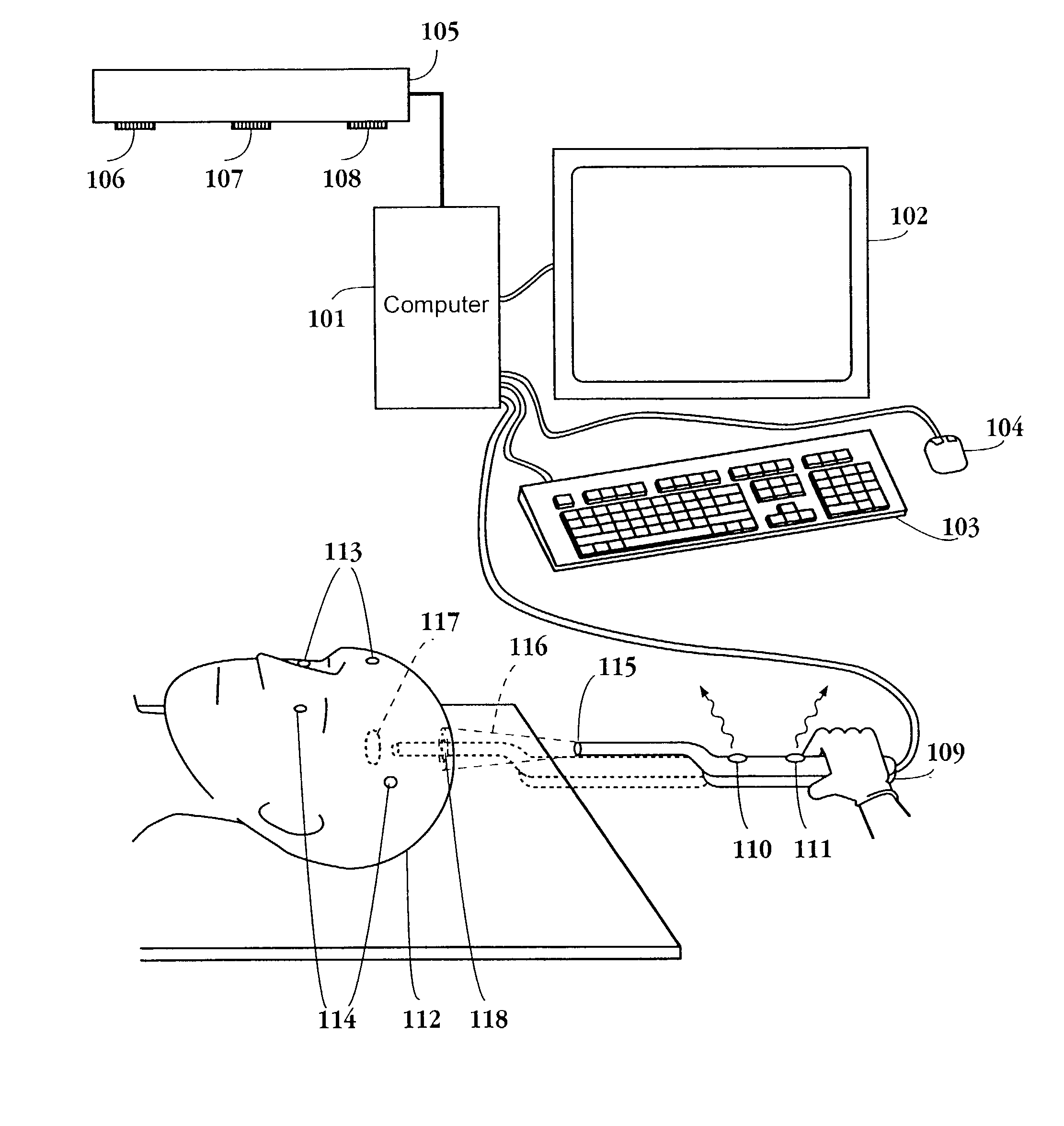
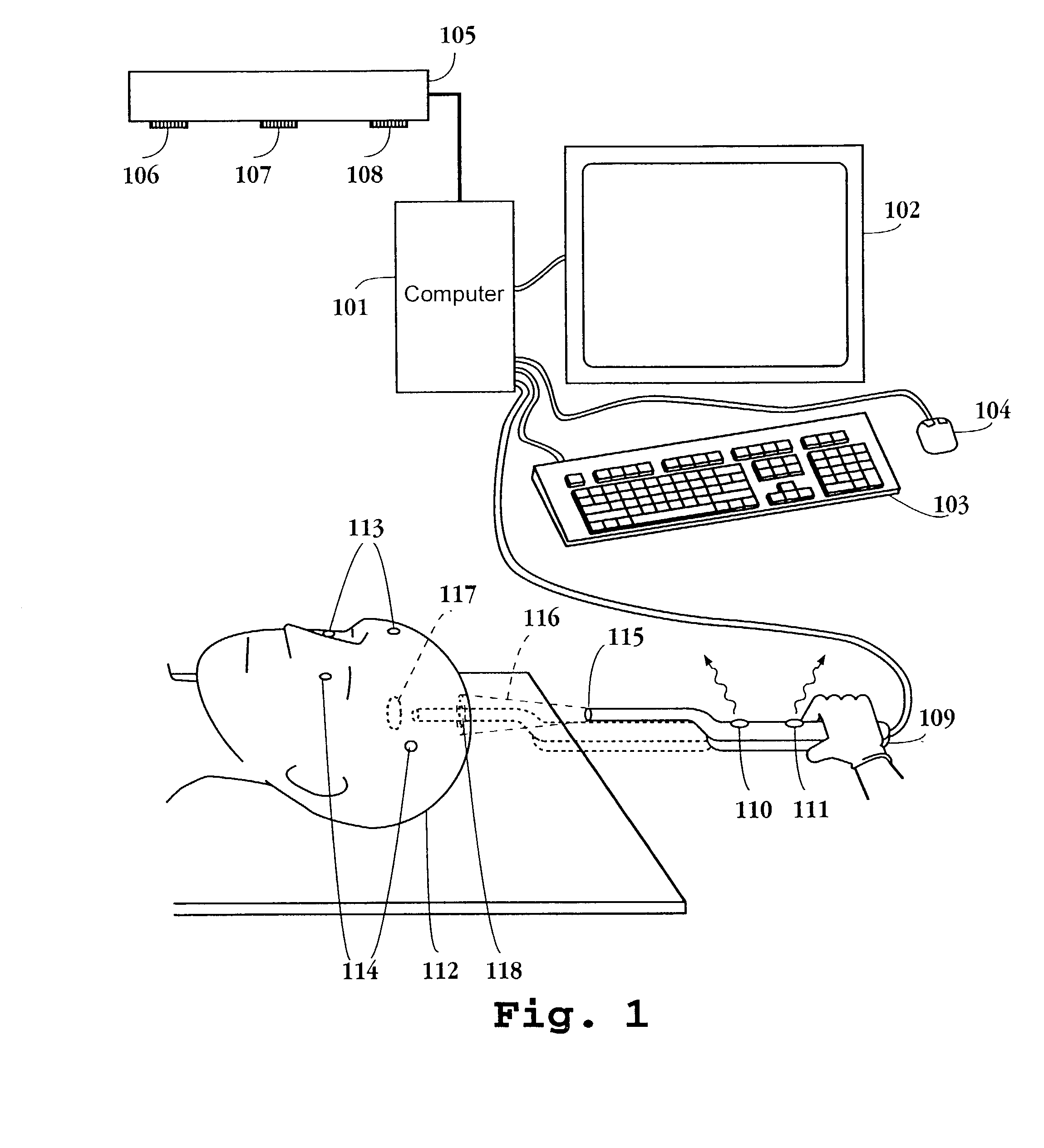
[0043]FIG. 1 shows the apparatus of the invention as used in performing or planning a neurosurgery operation. In this drawing the patient's head 112, has a tumor or lesion 117, which is the target object of the operation. Fiducial markers 113, 114 are attached to the head to enable registration of images generated by previously obtained scan data according to techniques familiar to persons of ordinary skill in the relevant art. A surgical probe or instrument 109 held by the surgeon is directed toward the tissues of interest. A computer 101 is connected to user input devices including a keyboard 103 and mouse 104, and a video display device 102 which is preferably a color monitor. The display device 102 is located such that it can be easily viewed by the surgeon during an operation, and the user input devices 103 and 104 are placed within easy reach to facilitate use during the surgery. The apparatus further includes a position tracking system, which is preferably an optical tracking...


PUM


Abstract

A surgical navigation system has a computer with a memory and display connected to a surgical instrument or pointer and position tracking system, so that the location and orientation of the pointer are tracked in real time and conveyed to the computer. The computer memory is loaded with data from an MRI, CT, or other volumetric scan of a patient, and this data is utilized to dynamically display 3-dimensional perspective images in real time of the patient's anatomy from the viewpoint of the pointer. The images are segmented and displayed in color to highlight selected anatomical features and to allow the viewer to see beyond obscuring surfaces and structures. The displayed image tracks the movement of the instrument during surgical procedures. The instrument may include an imaging device such as an endoscope or ultrasound transducer, and the system displays also the image for this device from the same viewpoint, and enables the two images to be fused so that a combined image is displayed. The system is adapted for easy and convenient operating room use during surgical procedures.

Description

CROSS REFERENCE TO RELATED APPLICATIONS[0001]This application is a continuation application of U.S. Pat. application Ser. No. 09 / 747,463 filed Dec. 22, 2000 now U.S. Pat. No. 6,591,130, which is a continuation of U.S. patent application Ser. No. 09 / 411,363 filed Sep. 30, 1999 now U.S. Pat. No. 6,167,296, issued Dec. 26, 2000, which is a continuation of U.S. patent application Ser. No. 08 / 884,289, filed Jun. 27, 1997, now abandoned, which claims the benefit of U.S. Provisional Application No. 60 / 020,664, filed Jun. 28, 1996; all of which are incorporated in their entirety herein by reference.BACKGROUND OF THE INVENTION[0002]1. Field of the Invention[0003]This invention pertains generally to systems and methods for generating images of three dimensional objects for navigation purposes, and more particularly to systems and methods for generating such images in medical and surgical applications.[0004]2. Description of the Background Art[0005]Precise imaging of portions of the anatomy is...

Claims


Application Information

Patent Timeline
IPC IPC(8): A61B5/05A61B5/06A61B19/00
CPCA61B5/06A61B19/52A61B19/5244A61B5/4504A61B19/50A61B19/56A61B2019/505A61B2019/507A61B2019/5255A61B2019/5268A61B2019/5272A61B2019/5276A61B2019/5278A61B2019/5289A61B2019/5291A61B2019/5295A61B5/064A61B34/10A61B34/20A61B34/25A61B90/36A61B2034/105A61B2034/107A61B2034/2055A61B2034/2068A61B2034/2072A61B2090/364A61B2090/365A61B2090/367A61B2090/378A61B2090/3782
Inventor SHAHIDI, RAMIN
Owner CICAS IP LLC
Why Eureka
Try Eureka