Ultrasound ablation apparatus with discrete staggered ablation zones

a technology of ultrasound ablation and ablation elements, which is applied in the field of ultrasound ablation equipment with discrete staggered ablation zones, can solve the problems of patient inability to achieve adequate blood pressure control according to guideline target values, inertia and patient non-compliance, and achieve the effect of reducing or eliminating the risk of renal artery/vein stenosis

Inactive Publication Date: 2011-06-09
ST JUDE MEDICAL
View PDF76 Cites 245 Cited by
  • Summary
  • Abstract
  • Description
  • Claims
  • Application Information

AI Technical Summary

Benefits of technology

[0007]Embodiments of the present invention are directed to an assembly of staggered ablation elements which are energized to produce ablation zones that span one or more open arc segments around the longitudinal axis, but the ablation zones of all the ablation elements projected longitudinally onto any lateral plane which is perpendicular to the longitudinal axis span a substantially closed loop around th

Problems solved by technology

Despite the availability of numerous safe and effective pharmacological therapies, including fixed-drug combinations, the percentage of patients achieving adequate blood-pressure control to guideline target values remains low.
Much failure of the pharmacological strategy to attain adequate blood-pressure control is attributed to both physician inertia and patient non-compliance and non-adherence to a lifelong pharmacological therapy

Method used


Image

  • Ultrasound ablation apparatus with discrete staggered ablation zones
  • Ultrasound ablation apparatus with discrete staggered ablation zones
  • Ultrasound ablation apparatus with discrete staggered ablation zones

Examples


Embodiment Construction

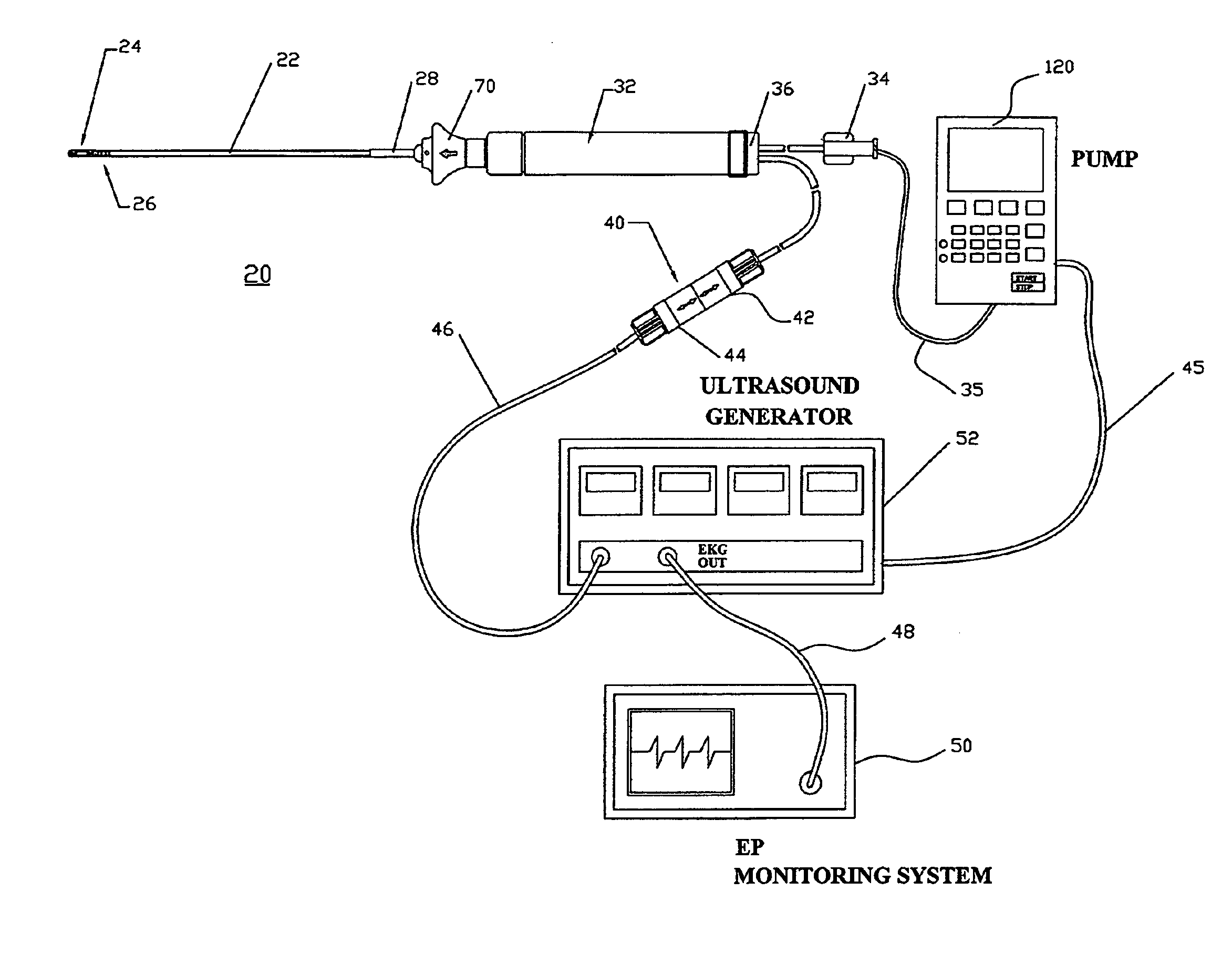
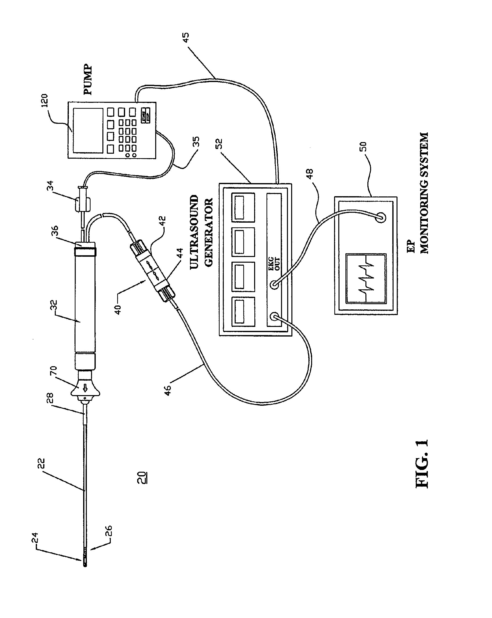
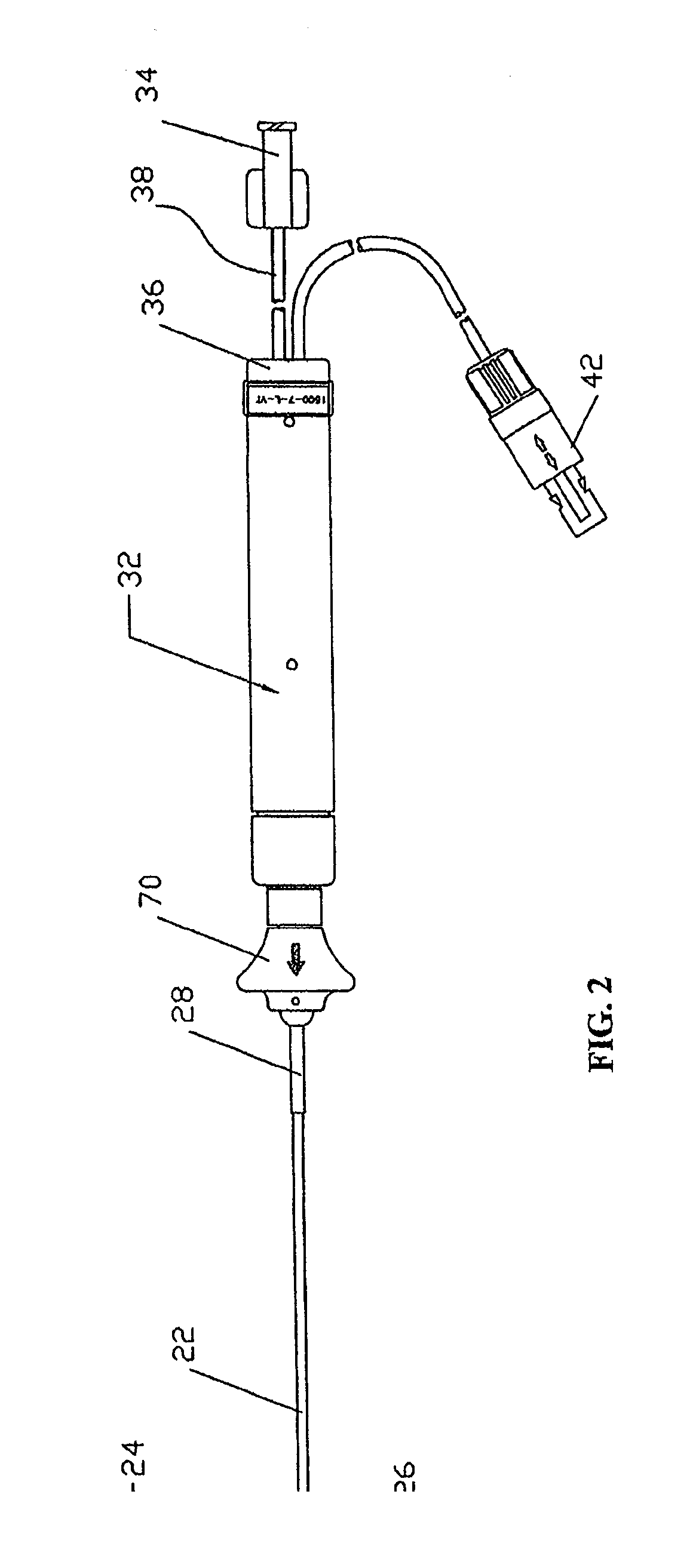
[0035]In the following detailed description of the invention, reference is made to the accompanying drawings which form a part of the disclosure, and in which are shown by way of illustration, and not of limitation, exemplary embodiments by which the invention may be practiced. In the drawings, like numerals describe substantially similar components throughout the several views. Further, it should be noted that while the detailed description provides various exemplary embodiments, as described below and as illustrated in the drawings, the present invention is not limited to the embodiments described and illustrated herein, but can extend to other embodiments, as would be known or as would become known to those skilled in the art. Reference in the specification to “one embodiment,”“this embodiment,” or “these embodiments” means that a particular feature, structure, or characteristic described in connection with the embodiment is included in at least one embodiment of the invention, a...


PUM


Abstract

An ablation apparatus comprises an ultrasonic transducer which includes a piezoelectric element having a cylindrical shape; a plurality of external electrodes disposed on the outer surface of the piezoelectric element; and at least one internal electrode disposed on the inner surface of the piezoelectric element. The at least one internal electrode provides corresponding internal electrode portions that are disposed opposite the external electrodes with respect to the piezoelectric element, the external electrodes and the at least one internal electrode to be energized to apply an electric field across the piezoelectric element. The ultrasonic ablation zones of the external electrodes are distributed in a staggered configuration so as to span one or more open arc segments around the longitudinal axis, and the ultrasound ablation zones of all external electrodes projected longitudinally onto any lateral plane which is perpendicular to the longitudinal axis span a substantially closed loop around the longitudinal axis.

Description

RELATED APPLICATIONS[0001]This application is a continuation-in-part of U.S. patent application Ser. No. 11 / 975,822, filed on Oct. 22, 2007, which is a continuation of U.S. patent application Ser. No. 10 / 845,798, filed on May 15, 2004 (now U.S. Pat. No. 7,285,116). This application is also a continuation-in-part of U.S. patent application Ser. No. 11 / 583,263, filed on Oct. 19, 2006, which is a continuation of U.S. patent application Ser. No. 09 / 975,269, filed on Oct. 11, 2001 (now U.S. Pat. No. 6,671,533). The entire disclosures of the above are incorporated herein by reference.BACKGROUND OF THE INVENTION[0002]The present invention relates generally to ablation devices and, more specifically, to an assembly of ablation elements arranged in a staggered configuration.[0003]Hypertension is a major global public health concern. An estimated 30-40% of the adult population in the developed world suffers from this condition. Furthermore, its prevalence is expected to increase, especially i...

Claims


Application Information

Patent Timeline
IPC IPC(8): A61B17/00
CPCA61B2017/22021A61B2017/320084A61B2018/00392A61N7/022A61N2007/003A61B2017/00247A61B5/01A61B5/0402A61B5/6852A61B17/2202A61B2017/00243A61N2007/0078A61B5/318
Inventor NGUYEN, THO HOANGHATA, CARYDE LA RAMA, ALANTRAN, VIVIANCHEN, PETER C.
Owner ST JUDE MEDICAL
Why Eureka
Try Eureka