

Ventilator mask and system
a technology of ventilation mask and mask, which is applied in the field of ventilation mask and system, can solve the problems of tubing drag, inability to operate the mask system, and mask to interfere with the bedding material, and achieve the effect of reducing or eliminating the risk of tubing drag
- Summary
- Abstract
- Description
- Claims
- Application Information
AI Technical Summary
Benefits of technology
Problems solved by technology
Method used
Image

Examples
Embodiment Construction
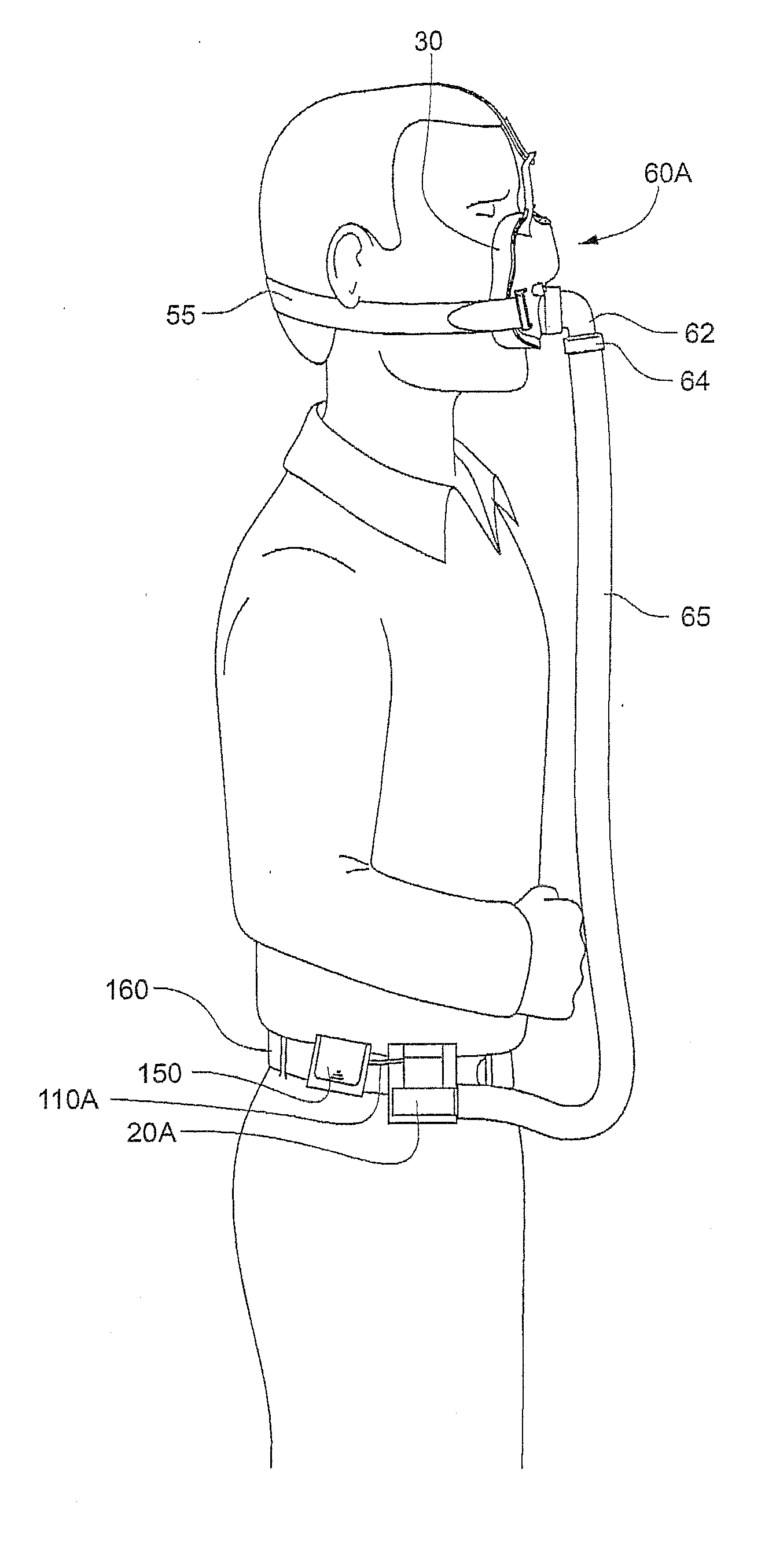
[0048]A CPAP system includes a mask and an air flow generator, wherein the air flow generator is provided to a wearer of the mask. In one embodiment, the air flow generator is mountable to a wearer's body (including a wearer's clothing). In another embodiment, the air flow generator is mounted on or provided to the mask.
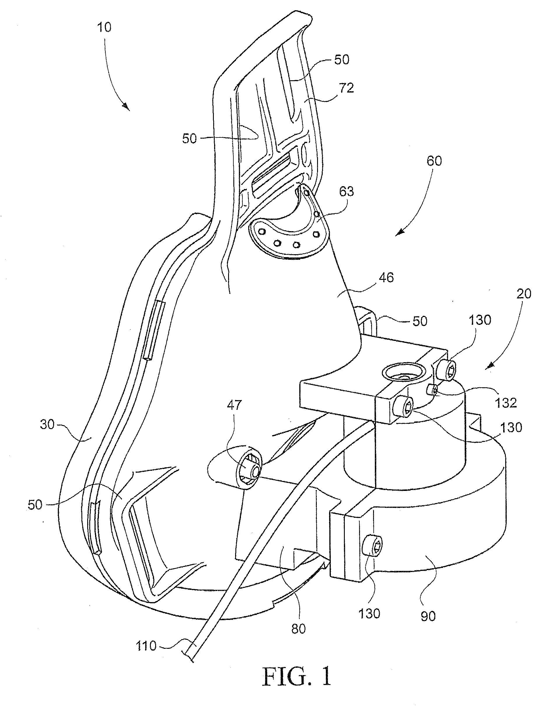
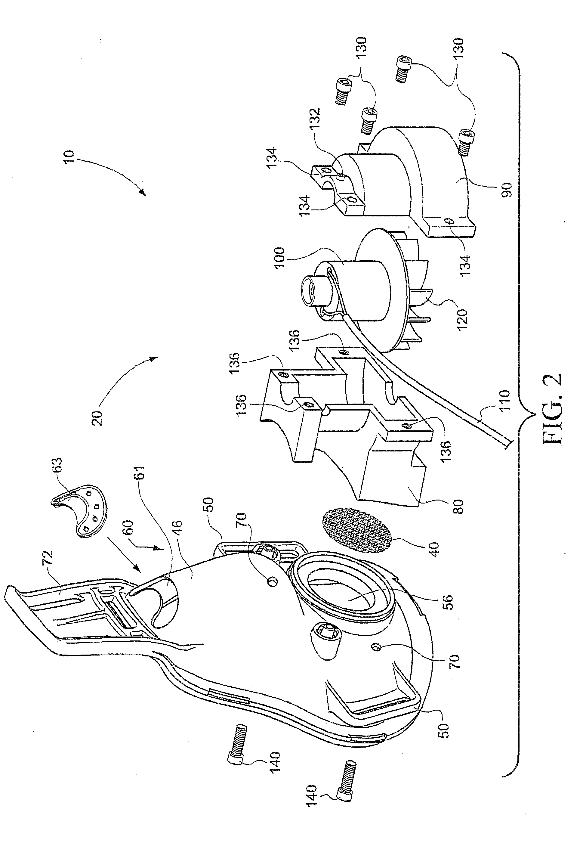
[0049]FIGS. 1-11B show several embodiments of CPAP systems according to the present invention.
[0050]Referring to FIG. 1, a CPAP system 10 includes a mask 60 provided with a cushion 30 and a shell 46 to form an air chamber in communication with the airways of a wearer. In this example, the mask 60 covers at least the oral and nasal region of a wearer. However, the mask 60 could also be a nasal mask and cover, for instance, only the nasal region or only the mouth region. In either case, it is preferable that the mask does not cover or interfere with the wearer's eyes or vision. The mask may include a vent opening 61 for CO2 gas washout, and one or more inlet ports 47 f...
PUM
 Abstract
Description
Claims
Application Information